Construction method for extra-deep foundation pit underground continuous wall

A technology of underground diaphragm wall and construction method, which is applied in basic structure engineering, sheet pile wall, earth mover/shovel, etc., can solve the problems affecting the accuracy and stability of underground wall groove formation, low strength and high compressibility

Active Publication Date: 2017-12-29
HONGRUN CONSTR GROUP STOCK
View PDF4 Cites 11 Cited by
  • Summary
  • Abstract
  • Description
  • Claims
  • Application Information

AI Technical Summary

Problems solved by technology

When the proposed site is a soft soil area, and it is necessary to build an ultra-deep underground diaphragm wall with a depth of more than 70 meters, the distribution of a large area of ​​thick soft soil will bring a series of geotechnical problems to the project construction. Widely distributed thick layer of soft soil , which has the characteristics of natural water content greater than or equal to the liquid limit, natural void ratio greater than or equal to 1.0, high compressibility, low strength, high sensitivity, low water permeability, etc. The anti-seepage ability of the wall directly affects the anti-

Method used


Image

  • Construction method for extra-deep foundation pit underground continuous wall
  • Construction method for extra-deep foundation pit underground continuous wall
  • Construction method for extra-deep foundation pit underground continuous wall

Examples


Embodiment Construction

[0031] The present invention will be described in detail below with reference to the accompanying drawings and examples.

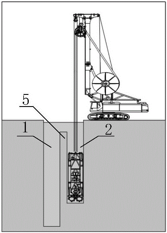
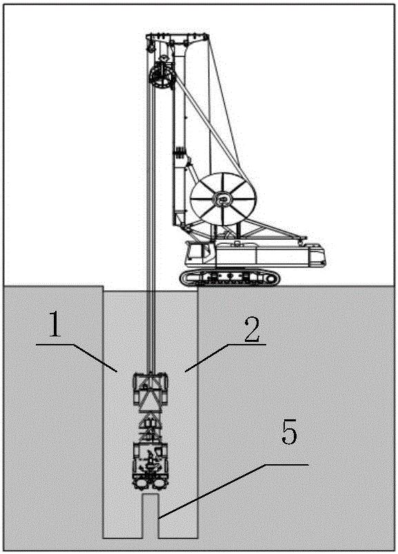
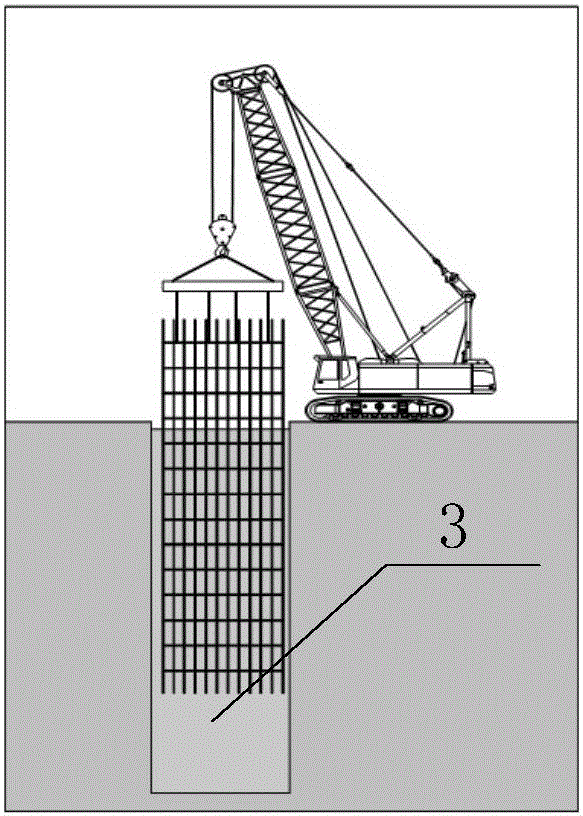
[0032] A kind of underground diaphragm wall construction method of the present invention, such as Figure 9 As shown, it mainly includes the construction preparation process, the groove forming process, the hole cleaning and grouting process, the joint wall brushing process, and the reinforcement cage installation and grouting process.

[0033] Among them, the construction preparation process is: find out the specific location of the foundation piles of the house before construction, and take excavation treatment and replacement measures for the existing shallow obstacles. Grouting reinforcement measures.

[0034] For the pile foundation within 1.0m of the left and right of the underground wall, use a vibrating hammer to clamp the channel steel to insert from around the pile to reduce the friction force of the pile, and then use a 600mm diameter locking p...


PUM

PropertyMeasurementUnit
Thicknessaaaaaaaaaa
Depthaaaaaaaaaa

Abstract

The invention discloses a construction method for an extra-deep foundation pit underground continuous wall. Firstly, a grab bucket is used for groove forming, and thus the cost can be saved; after a foundation pit reaches a certain depth, a groove milling machine is used for continuing groove forming, and thus groove forming precision can be guaranteed; further, in the groove forming process, a first hole is formed through the grab bucket and the groove milling machine, then a second hole is formed at a certain distance from the first hole, a partition wall between the two holes is milled, and finally a first-stage groove is formed; in this way, the grab bucket can apply balanced force when excavating each hole, the deviation is effectively rectified, and the perpendicularity of the formed groove is guaranteed; further, after a reinforcement cage is put into the first-stage groove and concrete is poured, the another first-stage groove is formed at a certain distance of the first-stage groove, and finally, a partition wall between the two first-stage grooves is milled through the groove milling machine; preferably, the edges of the concrete in the first-stage grooves in the two sides are milled while the partition walls are milled by the groove milling machine, and accordingly the raw edges are generated, therefore, the bonding tightness of the concrete in the two first-stage grooves and concrete in an intermediate groove can be improved, and the waterproof effect is achieved.

Description

technical field [0001] The invention belongs to the field of underground diaphragm wall construction, and in particular relates to a method for constructing an underground diaphragm wall of an ultra-deep foundation pit. Background technique [0002] The underground diaphragm wall is a kind of trenching machine used on the ground for basic engineering. Along the peripheral axis of the deep excavation project, under the condition of mud retaining wall, a narrow and long deep groove is excavated. After the groove is cleaned, steel bars are hung in the groove Cage, and then concrete is poured to form unit trough sections, and so on section by section, a continuous reinforced concrete wall is built underground as a structure for water interception, seepage prevention, load bearing and water retaining. When the proposed site is a soft soil area, and it is necessary to build an ultra-deep underground diaphragm wall with a depth of more than 70 meters, the distribution of a large ar...

Claims


Application Information

Patent Timeline
IPC IPC(8): E02D5/20E02F5/08
CPCE02D5/20E02F5/08
Inventor 楼岱赵余夫傅珺鲍廉梵陈洁袁醒神
Owner HONGRUN CONSTR GROUP STOCK
Why Eureka
Try Eureka