Gear shifting mechanism

A technology of speed change mechanism and transmission mechanism, applied in mechanical equipment, chain elements, transmission chain, etc., can solve the problems of high processing precision, complex structure, few gears, etc. Effect

Pending Publication Date: 2017-12-29
梁建
View PDF0 Cites 0 Cited by
  • Summary
  • Abstract
  • Description
  • Claims
  • Application Information

AI Technical Summary

Problems solved by technology

[0002] The existing parallel shaft gear transmission mechanism has the problems of large volume, small torque, and few gears; at the same time, the existing planetary gear transmission mechanism has the problems of complex structure and high machining accuracy requirements

Method used


Image

  • Gear shifting mechanism
  • Gear shifting mechanism
  • Gear shifting mechanism

Examples


Embodiment 1

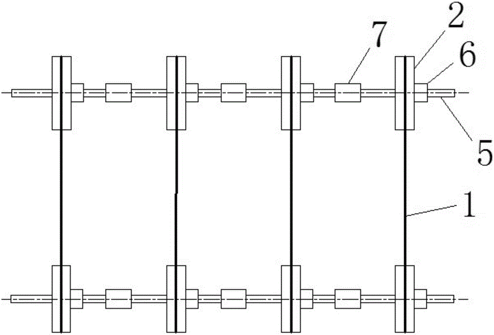
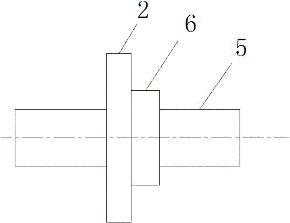
[0055] Such as figure 1 As shown, a speed change mechanism includes two parallel and opposite first shaft systems, and the first shaft systems include several such as image 3 The transmission mechanism shown, the transmission mechanism includes such as Figure 4 Shown shaft 5, the sprocket 2 is set on the shaft 5, and the shaft 5 and the sprocket 2 are provided with Figure 5 The first connecting sleeve 6 shown, the shaft 5 and the first connecting sleeve 6, the first connecting sleeve 6 and the sprocket 2 are clearance fit, the shaft 5 and the first connecting sleeve 6, the first connecting sleeve 6 and the sprocket 2 They are all keyed connections; the two adjacent transmission mechanisms on the first shafting system are connected through such as Figure 6 The second connecting sleeve 7 shown is connected, the second connecting sleeve 7 and the shaft 5 are in clearance fit, and the second connecting sleeve 7 and the shaft 5 are in a key connection; the sprockets 2 on the ...

Embodiment 2

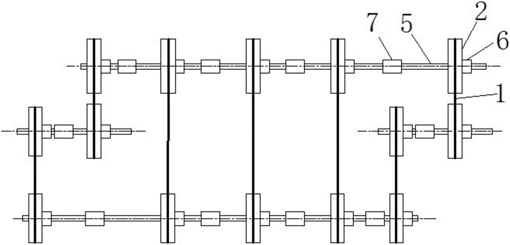
[0082] It differs from Embodiment 1 in that: as figure 2 As shown, the speed change mechanism also includes a second shaft system and a third shaft system, the second shaft system includes two transmission mechanisms, the two transmission mechanisms are connected through the second connecting sleeve 7, and the third shaft The system includes two transmission mechanisms, the two transmission mechanisms are connected through the second connecting sleeve 7, the second shaft system is respectively connected to one end of the two first shaft systems through two chains 1, and the third shaft system is connected through two chains 1 Connect the other ends of the two first shaft systems respectively.

[0083] In this embodiment, the second axis and the third shaft system serve as torque input and torque output respectively, and play a role in flexibly arranging the input and output shafts.


PUM


Abstract

The invention discloses a transmission mechanism, which belongs to two parallel and opposite first shaft systems. The first shaft system includes several transmission mechanisms. The transmission mechanism includes a shaft, and a sprocket is set on the shaft. There is a first connecting sleeve between the shaft and the sprocket, and the shaft and the first connecting sleeve, and the first connecting sleeve and the sprocket are all in clearance fit, and the shaft and the first connecting sleeve, and the first connecting sleeve and the sprocket are all connected by keys ; The two adjacent transmission mechanisms on the first shaft system are connected through the second connecting sleeve, the second connecting sleeve and the shaft are clearance fit, and the second connecting sleeve and the shaft are keyed; the two first The sprockets on the shaft system are respectively connected by several chains; the invention is reasonable in design and convenient in manufacture, and can solve the problems of large volume, few gears and high manufacturing precision requirements in the existing transmission mechanism.

Description

technical field [0001] The invention relates to the field of transmission equipment, in particular to a speed change mechanism. Background technique [0002] The existing parallel shaft gear transmission mechanism has the problems of large volume, small torque and few gears; at the same time, the existing planetary gear transmission mechanism has the problems of complex structure and high machining accuracy requirements. Contents of the invention [0003] In order to solve the above problems, the present invention provides a speed change mechanism. [0004] In order to achieve the above object, the technical solution adopted by the present invention is as follows: a speed change mechanism includes two parallel and opposite first shaft systems, the first shaft system includes several transmission mechanisms, and the transmission mechanisms include shafts, A sprocket is set on the shaft, and a first connecting sleeve is arranged between the shaft and the sprocket. The shaft...

Claims


Application Information

Patent Timeline
Patent Type & Authority Applications(China)
IPC IPC(8): F16H9/24F16G13/06F16G15/00
CPCF16H9/24F16G13/06F16G15/00
Inventor 梁建
Owner 梁建
Why Eureka
Try Eureka