Cable temperature monitoring device

A monitoring device and cable technology, applied in measurement devices, thermometers, testing dielectric strength, etc., can solve the problems of multi-point or distributed measurement signal transmission, which is difficult to solve, temperature measurement is susceptible to environmental interference, and high-voltage safety issues. Achieve the effect of eliminating hidden safety hazards, avoiding fault expansion, and reducing workload

Pending Publication Date: 2017-12-29
浙江华普电缆有限公司
View PDF0 Cites 2 Cited by
  • Summary
  • Abstract
  • Description
  • Claims
  • Application Information

AI Technical Summary

Problems solved by technology

[0003] To solve the problem of temperature rise during cable operation, traditional temperature measurement methods generally use thermocouples or infrared monitoring, but these methods, such as: thermocouples that transmit signals through metal wires, have high-voltage safety problems, and non-contact temperature measurement based on infrared technology There are problems such as inconvenient installation, and temperature measurement is susceptible to environmental interference. In addition, the above two measurement methods have the problem of multi-point or distributed measurement signal transmission that is difficult to solve. Therefore, a cable temperature monitoring device with high reliability is appears to be particularly important

Method used


Image

  • Cable temperature monitoring device
  • Cable temperature monitoring device
  • Cable temperature monitoring device

Examples


Embodiment Construction

[0017] The present invention is not limited by the following examples, and specific implementation methods can be determined according to the technical solutions of the present invention and actual conditions.

[0018] Below in conjunction with embodiment and accompanying drawing, the present invention will be further described:

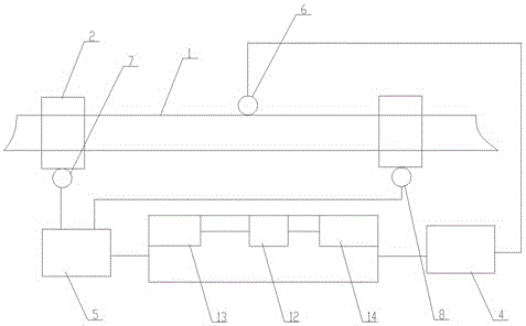
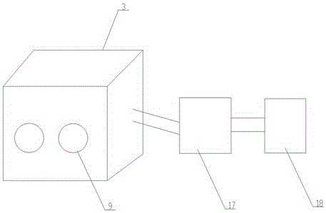
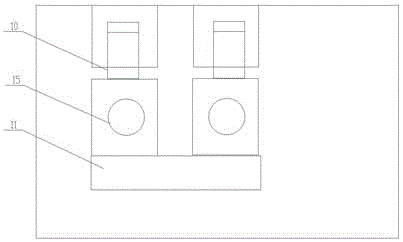
[0019] Such as figure 1 , 2 As shown, the cable temperature monitoring device includes a cable 1, two cable joints 2 arranged at both ends of the cable 1, an insulating box 3, a first signal collector 4, a second signal collector 5 and a control unit, the cable 1 The first temperature sensor 6 is provided on the top, the second temperature sensor 7 and the third temperature sensor 8 are respectively provided on the two cable joints 2, and two cable joints 2 are inserted on one side of the insulating box body 3 hole 9, two screw clamping terminal posts 10 are arranged in the insulating box body 3, and the bottom of the screw clamping terminal post 1...


PUM


Abstract

The invention relates to the technical field of cable temperature monitoring, and in particular to relates to a cable temperature monitoring device. The cable temperature monitoring device comprises a cable, two cable joints disposed at two ends of the cable, an insulation box body, a first signal collecting device, a second signal collecting device, and a control unit. The cable is provided with a first temperature sensor. The two cable joints are respectively provided with a second temperature sensor and a third temperature sensor. One side surface of the insulation box body is provided with two cable joint inserting holes. Two spiral clamping type terminal binding posts are disposed in the insulation box body. The bottom of the spiral clamping type terminal binding post is connected to a conductance sheet, which is respectively and electrically connected to the detection probe of the corresponding second temperature sensor and the third temperature sensor. The invention is advantageous in that through the real-time monitoring of the change of cable temperature, workers in charge of regulation and control and operation can be reminded in time when the cable is at high temperature, and thereby faults can be prevented, and fault enlargement due to cable breakdown can be prevented.

Description

technical field [0001] The invention relates to the technical field of cable temperature monitoring, in particular to a cable temperature monitoring device. Background technique [0002] As modern urban construction puts forward higher requirements for power transmission, the use of power cables has increased sharply, causing the voltage and current of cable loads to increase continuously, resulting in a rise in temperature during cable operation; in addition, in cable joints and power systems During abnormal operations such as overloading and short circuit tripping, the temperature rise of the cable may also be abnormal, forming a safety hazard. Therefore, an effective way to monitor the temperature change of the cable during work and operation is the key to ensuring the safety of the power system. It is an important issue, and it is also of great significance to the production and life of using electricity. [0003] To solve the problem of temperature rise during cable op...

Claims


Application Information

Patent Timeline
Patent Type & Authority Applications(China)
IPC IPC(8): G01K13/00G01R31/12
CPCG01K13/00G01R31/1272
Inventor 池利利
Owner 浙江华普电缆有限公司
Why Eureka
Try Eureka