
LED screen test power supply control circuit and method based on precise quantized power-on sequence

A technology for power-on sequence and power supply testing, which is applied to instruments, static indicators, etc., can solve problems such as inaccurate power-on time, different power-on time, large capacitance error, etc., to improve voltage quality, ripple suppression, and power The effect of low consumption

Active Publication Date: 2017-12-29
WUHAN JINGCE ELECTRONICS GRP CO LTD
View PDF5 Cites 8 Cited by
  • Summary
  • Abstract
  • Description
  • Claims
  • Application Information

AI Technical Summary

Problems solved by technology

[0003] (1) The power-on time control depends on the capacitance parameters, the capacitance error is large, and the power-on time is not accurate enough;
[0004] (2) For the same set of control parameters, the actual control accuracy varies with the output voltage and load current, which directly leads to different power-on time under the same control parameters and different loads.

Method used


Image

  • LED screen test power supply control circuit and method based on precise quantized power-on sequence
  • LED screen test power supply control circuit and method based on precise quantized power-on sequence
  • LED screen test power supply control circuit and method based on precise quantized power-on sequence

Examples


Embodiment approach

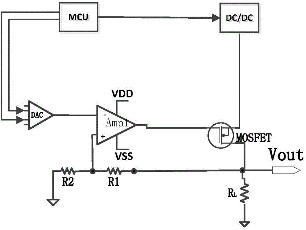
[0039] The present invention also proposes a method for accurately quantifying the power-on sequence of the LED screen to test the power supply control circuit, which is applicable to the above four implementation modes, and specifically includes the following steps:

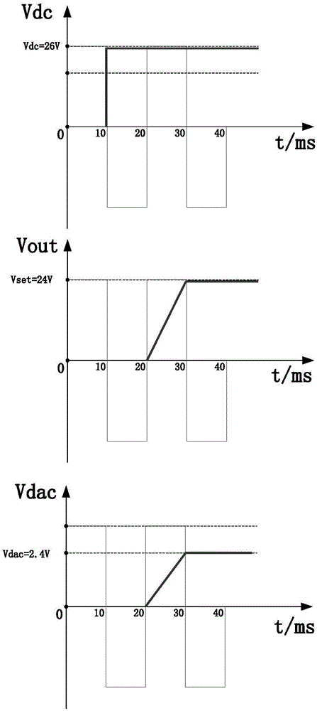
[0040] 1) Set the output voltage Vdc of the DC / DC power supply module according to the value of the output voltage Vout, the voltage value required by the LED screen power supply = output voltage Vout; the output voltage Vdc of the DC / DC power supply module = output voltage Vout + voltage difference, the voltage difference is not greater than 2V.

[0041] 2) Set the output value Vdac of the DAC digital-to-analog converter according to the value of the output voltage Vout and the amplification ratio b, Vout=b*Vdac, and set the waveform slope a according to the power-on time Tset required by the LED screen power supply, a=Vdac / Tset .

[0042] 3) The MCU outputs the voltage to the DC / DC power module, and outputs t...


PUM


Abstract

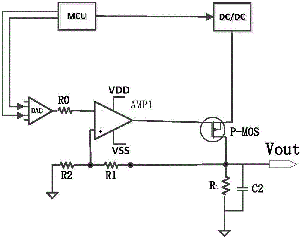
The invention discloses an LED screen test power supply control circuit and method based on a precise quantized power-on sequence. The control circuit includes an MCU of which the output end is connected with a DC / DC power supply module and a DAC (Digital-to-Analog Converter). The output end of the DAC is connected with the negative input end of an operational amplifier AMP1. The positive input end of the operational amplifier AMP1 is connected with a voltage divider circuit. The output end of the operational amplifier AMP1 is connected with one input end of an MOS tube. The output end of the DC / DC power supply module is connected with the other input end of the MOS tube. A third end of the MOS tube is an output end which outputs a voltage Vout. The DAC inputs a voltage control waveform to the operational amplifier AMP1 under the control of the MCU, and the voltage control waveform includes the voltage value and the power-on time Tset required by an LED screen power supply. The operational amplifier AMP1 linearly amplifies the received voltage control waveform, and outputs the amplified voltage control waveform to the MOS tube. The DC / DC power supply module outputs a voltage Vdc to the MOS tube under the control of the MCU.

Description

technical field [0001] The invention relates to the technical field of LED driving, in particular to an LED screen test power supply control circuit and method for accurately quantifying the power-on sequence. Background technique [0002] During the LED screen test process, multiple power supplies are often required. Different power supply uses and output values ​​are different. During use, different power supplies are often required to precisely control the timing when they are powered on. However, in the existing power supply equipment, whether it is a switching power supply or a linear voltage regulator, the power-on time and waveform depend on fixed hardware parameters. A common solution is to design a switch circuit on the output port of the power supply, use PWM to control the switch conduction, and combine the output capacitor filter to control the power-on time. The disadvantages of this control method are: [0003] (1) The power-on time control depends on the c...

Claims


Application Information

Patent Timeline
Patent Type & Authority Applications(China)
IPC IPC(8): G09G3/00
CPCG09G3/006
Inventor 胡国锋
Owner WUHAN JINGCE ELECTRONICS GRP CO LTD
Learn More