Pipe joint

A technology of pipe joints and nozzles, which is applied in the field of pipe joints, can solve the problems of labor and other issues, and achieve the effect of safe work and easy connection operations

Active Publication Date: 2018-01-02
MEIWA IND CO LTD
View PDF6 Cites 2 Cited by
  • Summary
  • Abstract
  • Description
  • Claims
  • Application Information

AI Technical Summary

Problems solved by technology

In such a case, in the above-mentioned joint structure, in order to repair the damaged part, it is necessary to remove the first pipe body as a whole, and labor is also required for this.

Method used


Image

  • Pipe joint
  • Pipe joint
  • Pipe joint

Examples


Embodiment 1

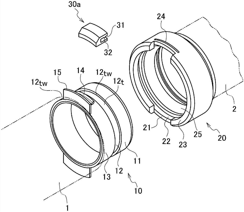
[0035] The pipe joint of the present invention is used to connect one pipe (hereinafter referred to as the first pipe body 1 . figure 1is shown by a double-dotted line. ) and another pipe (hereinafter referred to as the second pipe body 2. It is also shown with a two-dot dash line.).

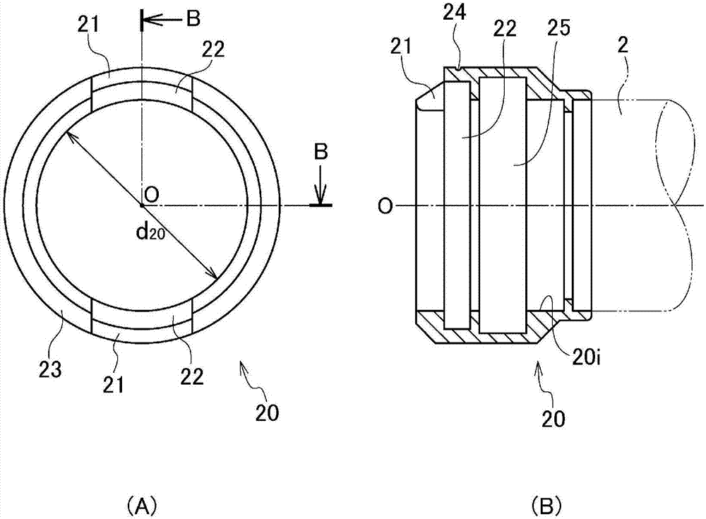
[0036] Figure 1~4 (remove figure 2 (Except for (B)) shows the pipe joint of Example 1. The pipe joint mainly includes a first sleeve 10 connected to the first pipe body 1 and a second sleeve 20 connected to the second pipe body 2 and having an opening capable of accommodating the first sleeve 10 . Moreover, the connection between the first and second sleeves 10, 20 and the first and second pipe bodies 1, 2 is realized by, for example, welding, bonding or other known connection methods.

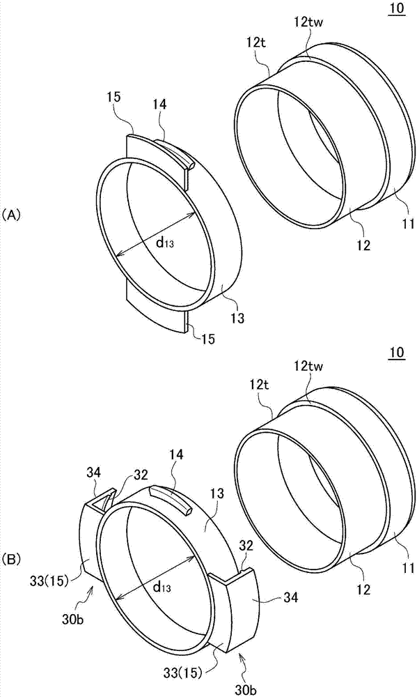
[0037] The first sleeve 10 such as Figure 4 As shown in (A), it may also include a plurality of cylindrical bodies (the first, second, and third nozzles 11, 12, and 13 in this embodiment). and, figure...

Embodiment 2

[0047] Figure 5 (A) to (D) show the pipe joint of Example 2. The pipe joint of Embodiment 2 is also the same as Embodiment 1, and has a first sleeve 10 connected to the first pipe body 1 and a second sleeve 20 connected to the second pipe body 2 . The structures of the first sleeve 10 and the second sleeve 20 in the second embodiment are substantially the same as those of the components 10 and 20 adopted in the first embodiment, and will not be described again. Here, the difference between Embodiment 2 and Embodiment 1 lies in the structure of the anti-loosening component 30b and the position of the manipulation member provided on the outer peripheral surface of the third nozzle 13, and the following two points will be explained emphatically. and, figure 2 (B) is the perspective view of the 3rd nozzle 13 of Example 2, and the 1st sleeve 10 including the fall-off preventing member 30b provided thereon.

[0048] For example, if figure 2 As shown in (B), the anti-loosening...


PUM


Abstract

Provided is a pipe joint configured so that the pipe joint can be handled with increased efficiency during the work of connecting pipe bodies and so that the repair of a constituting part broken during connection or maintenance can be facilitated. A pipe joint is provided with: a first sleeve 10 connected to a first pipe body 1; and a second sleeve 20 connected to a second pipe body 2 and having an opening capable of receiving the first sleeve 10. The first sleeve 10 is provided with a first collar 11, a second collar 12, and a third collar 13 which has an inner diameter d13 larger than the outer diameter D12 of the second collar 12 and which is supported by both walls 12tw of a groove 12t so as to be rotatable in the outer circumferential direction, the groove 12t being formed by the first collar 11, the second collar 12, etc. The third collar 13 is provided with at least one first protrusion 14 protruding outward radially. The second sleeve 20 is provided with: a cutout 21 capable ofreceiving the first protrusion 14; and a first recess 22 for receiving the first protrusion 14 through the cutout 21 and rotatably guiding the first protrusion 14 in the inner circumferential direction of the second sleeve 20.

Description

technical field [0001] The present invention relates to a pipe joint for forming a pipeline in a temporary piping route temporarily installed instead of piping in sewer construction, gas construction, or piping replacement engineering in a factory. Background technique [0002] When performing the above-mentioned piping work, it is generally desired that the end of a certain pipe (first pipe body) can be easily and reliably connected (disassembled as required) to the end of another pipe (second pipe body). For example, as a conventional pipe joint, Patent Documents 1 to 2 are listed below as examples, and the contents disclosed in each document are summarized. [0003] In the pipe joints of Patent Documents 1 and 2, in order to connect to a certain pipe (first pipe body), a sleeve having an opening capable of accommodating the end of the first pipe body is attached to the other pipe (second pipe body). At least one protrusion protruding outward in the radial direction is pr...

Claims


Application Information

Patent Timeline
Patent Type & Authority Applications(China)
IPC IPC(8): F16L37/24
CPCF16L37/24
Inventor 关根繁明
Owner MEIWA IND CO LTD
Why Eureka
Try Eureka