An unmanned aerial vehicle used for panoramic photography

A panoramic shooting and UAV technology, applied in the field of virtual reality, can solve the problems of poor framing effect, inconvenient drone, and easy damage of the fuselage, and achieve good framing effect, improved safety, and stable structure.

Inactive Publication Date: 2018-01-05
BEIJING MELUO QICHENG TECH
View PDF6 Cites 8 Cited by
  • Summary
  • Abstract
  • Description
  • Claims
  • Application Information

AI Technical Summary

Problems solved by technology

[0011] The main problem to be solved by this application is to provide a drone with simple and convenient use, good user experience, comprehensive viewfinder pictures and good effects, undamaged fuselage, high safety in use, stab

Method used


Image

  • An unmanned aerial vehicle used for panoramic photography
  • An unmanned aerial vehicle used for panoramic photography
  • An unmanned aerial vehicle used for panoramic photography

Examples


Embodiment 1

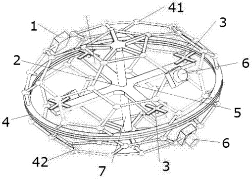
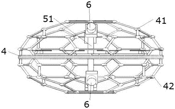
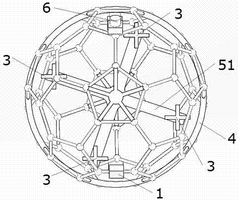
[0039] Such as figure 1 The structural representation of the unmanned aerial vehicle provided by the present invention, figure 2 The front view of the drone provided by the present invention, image 3 As shown in the top view of the unmanned aerial vehicle provided by the present invention, a kind of unmanned aerial vehicle for panoramic shooting, especially suitable for panoramic shooting, includes a control device (not shown in the figure), a power supply 1, and is electrically connected to the power supply 1 The electric device 2 and the propeller 3 connected with the electric device 2 are characterized in that it also includes a casing 4 and a fuselage 5 body connected in the casing 4, and the electric device 2 and the propeller 3 are connected to the machine. Body 5, the shell 4 is a hollow structure, the shell 4 is provided with a camera device 6, the control device is electrically connected with the electric device 2 and the camera device 6, the electric device 2 and ...

Embodiment 2

[0042] Such as figure 1 The structural representation of the unmanned aerial vehicle provided by the present invention, figure 2 The front view of the drone provided by the present invention, image 3 As shown in the top view of the unmanned aerial vehicle provided by the present invention, a kind of unmanned aerial vehicle for panoramic shooting, especially suitable for panoramic shooting, includes a control device (not shown in the figure), a power supply 1, and is electrically connected to the power supply 1 The electric device 2 and the propeller 3 connected with the electric device 2 are characterized in that it also includes a casing 4 and a fuselage 5 body connected in the casing 4, and the electric device 2 and the propeller 3 are connected to the machine. Body 5, the shell 4 is a hollow structure, the shell 4 is provided with a camera device 6, the control device is electrically connected with the electric device 2 and the camera device 6, the electric device 2 and ...


PUM


Abstract

The objective of the invention is to provide an unmanned aerial vehicle used for panoramic photography. The unmanned aerial vehicle is particularly suitable for panoramic photography. The unmanned aerial vehicle includes a control device, a power supply, an electric actuator electrically connected to the power supply, and propellers connected to the electric actuator. The unmanned aerial vehicle is characterized in that the unmanned aerial vehicle also includes a shell and a vehicle main body connected to the inside of the shell; the electric actuator and the propellers are connected to the vehicle main body; the shell has a hollow structure, and is provided with photographing devices; the control device is electrically connected to the electric actuator and the photographing devices; theelectric actuator and the propellers are inside the shell; and a scheme including a middle frame and two hollow hemispheres is adopted, thus effectively protecting the vehicle main body of the unmanned aerial vehicle, preventing possible influences of collision on the unmanned aerial vehicle, improving safety and effectively avoiding possible harm to pedestrians when the unmanned aerial vehicle descends or falls.

Description

technical field [0001] The invention belongs to the technical field of virtual reality, and specifically refers to an unmanned aerial vehicle for panoramic shooting. Background technique [0002] The equipment required for panoramic aerial photography mainly includes aircraft and 360-degree panoramic cameras. At present, most of the aircraft capable of panoramic photography on the market use multi-rotor aircraft or helicopters, and a panoramic camera is installed on the nose or belly of the aircraft to realize the function of panoramic aerial photography. [0003] Since the imaging of the panoramic camera is a 360-degree spherical surface, that is, all the scenes surrounding the camera in space are captured into the camera lens. After the camera is installed on the aerial vehicle, the aircraft itself will inevitably block the panoramic camera to a certain extent, resulting in the captured 360-degree The spherical panoramic image includes a partial image of the aircraft fuse...

Claims


Application Information

Patent Timeline
IPC IPC(8): B64C27/08B64C27/20B64D47/08
Inventor 姜威杨子路
Owner BEIJING MELUO QICHENG TECH
Why Eureka
Try Eureka