
Drying equipment provided with stirring mechanism

A technology of drying equipment and stirring mechanism, which is applied in the direction of drying, drying machine, lighting and heating equipment, etc., which can solve the problems of insufficient heat, low drying efficiency of production materials, uneven internal temperature, etc., and achieve energy saving and energy saving Energy consumption, speed-up effect

Inactive Publication Date: 2018-01-05
弘毅天承知识产权股份有限公司
View PDF0 Cites 3 Cited by
  • Summary
  • Abstract
  • Description
  • Claims
  • Application Information

AI Technical Summary

Problems solved by technology

[0004] When bamboo products are processed, the materials need to be dried to prevent mildew from affecting the quality of bamboo products. However, the existing drying equipment only sets a heat source at the bottom of the drying equipment, resulting in uneven internal temperature. When the temperature is too low, there may be Insufficient heat, resulting in low drying efficiency of materials

Method used


Image

  • Drying equipment provided with stirring mechanism
  • Drying equipment provided with stirring mechanism
  • Drying equipment provided with stirring mechanism

Examples


Embodiment 1

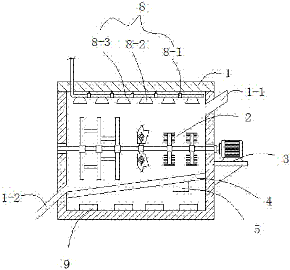
[0023] Such as Figure 1 to 2 As shown, this embodiment provides a drying equipment with a stirring mechanism, including a drying chamber 1, a feed port 1-1 and a discharge port 1-2 communicating with the interior of the drying chamber 1, characterized in that: The drying chamber 1 is provided with a vibrating baffle 4 obliquely, the discharge port 1-2 is located on the drying chamber 1 on the lower side of the vibrating baffle 4, and the vibrating baffle 4 divides the drying chamber 1 into upper materials The top of the upper material cavity is equipped with a return air system 8, the upper material cavity is equipped with a horizontal stirring mechanism 2, the upper material cavity is equipped with a driving mechanism 3 that drives the horizontal stirring mechanism 2 to rotate, and the lower heating cavity is arranged There is a heating element 9.

[0024] The return air system 8 includes a main return air pipe 8-3 that is clamped to the top of the upper material cavity throug...

Embodiment 2

[0027] This embodiment is further optimized on the basis of embodiment 1, specifically:

[0028] The return air collecting cover 8-2 has a cone-like structure with a small upper part and a larger lower part.

[0029] A vibration mechanism 5 is provided under the vibration partition 4.

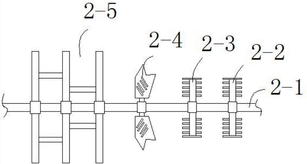
[0030] The said horizontal stirring mechanism 2 includes a horizontal stirring shaft 2-1, and a stirring assembly A2-5, a stirring assembly B2-4, a stirring assembly C2-3 and a stirring assembly D2-2 are arranged in order from left to right on the transverse stirring shaft. The stirring assembly C2-3 and the stirring assembly D2-2 have the same mechanism.

[0031] The stirring assembly C2-3 includes a stirring rod symmetrically arranged on the transverse stirring shaft 2-1, and a plurality of stirring teeth are provided on the stirring rod.

[0032] The mixing assembly B2-4 includes heterosexual mixing blades symmetrically arranged on the transverse mixing shaft 2-1, the heterosexual mixing blades are m...


PUM


Abstract

The invention discloses a drying equipment with a stirring mechanism, which relates to the technical field of drying equipment. The invention comprises a drying chamber, a material inlet and a material outlet connected to the inside of the drying chamber, and the inside of the drying chamber is inclined A vibrating partition is provided, and the outlet is located on the drying chamber on the lower side of the vibrating partition. The vibrating partition divides the drying chamber into an upper material chamber and a lower heating chamber, and a return air system is installed on the top of the upper material chamber. , the upper material chamber is provided with a horizontal stirring mechanism, the upper material chamber is provided with a drive mechanism to drive the horizontal stirring mechanism to rotate, and the lower heating chamber is provided with a heating source. The invention has the advantages of simple structure, uniform baking, high baking efficiency and The advantage of saving energy.

Description

Technical field [0001] The invention relates to the technical field of drying equipment, and more specifically to a drying equipment with a stirring mechanism. Background technique [0002] Chinese people have always loved bamboo, and China is also the earliest country in the world to research, cultivate and use bamboo. From the huge role of bamboo in the development of Chinese history and culture and the formation of spiritual culture, the long-standing relationship between bamboo and Chinese poetry, calligraphy, painting and garden construction, and the close relationship between bamboo and people’s lives, it is not difficult to see that China deserves to be called "bamboo". Civilized country". [0003] Bamboo products refer to products made from bamboo as processing raw materials. Most of them are daily necessities, such as bamboo baskets, bamboo screens, bamboo fences, 筲箕, bamboo steamers, cooking brooms, bamboo dustpans, bamboo dust buckets, bamboo mats, bamboo beds, bamboo ...

Claims


Application Information

Patent Timeline
IPC IPC(8): F26B11/16F26B23/00F26B25/04
Inventor 樊明伟
Owner 弘毅天承知识产权股份有限公司
Learn More