Supercharge Your Innovation With Domain-Expert AI Agents!

An all-metal eddy current position sensor and its solution to temperature drift

A solution, eddy current technology, applied in the direction of using electrical devices, instruments, measuring devices, etc., can solve problems such as unsolvable temperature drift, unsuitable for detection, expensive cost, etc., to achieve a wide range of applications, increase market competitiveness, and protect the environment The effect of adaptability

Active Publication Date: 2019-06-14
SHANGHAI LANBAO SENSING TECH
View PDF5 Cites 0 Cited by
  • Summary
  • Abstract
  • Description
  • Claims
  • Application Information

AI Technical Summary

Problems solved by technology

This method only considers the non-metallic package of the probe and the situation that there is no metal equipment near the installation environment. It fails to conduct research and analysis on the metal package of the sensor probe and the presence of metal around the installation, which has poor versatility.
2. Add a non-inductive non-inductive coil with the same resistance value to sense the temperature change to compensate. This method can only eliminate the temperature drift caused by the temperature change of the detection coil resistance itself, and fails to adjust the temperature of the shell and the resistivity of the detection body. drift compensation
However, this method only adds metal materials around the side ends of the surrounding coils, and is not suitable for detection when the probe is fully metal-packaged.
4. Use some expensive high-temperature-resistant alloy materials to wind the coil. The structure of this probe is the same as that of ordinary probes, but the cost is expensive. Although it can reduce the temperature drift of the detection coil itself, it still cannot solve the temperature caused by the metal packaging of the probe. drift

Method used


Image

  • An all-metal eddy current position sensor and its solution to temperature drift
  • An all-metal eddy current position sensor and its solution to temperature drift
  • An all-metal eddy current position sensor and its solution to temperature drift

Examples


Embodiment Construction

[0047]The following is a detailed description of the embodiments of the present invention. This embodiment is carried out based on the technical solution of the present invention, and provides detailed implementation methods and specific operation processes.

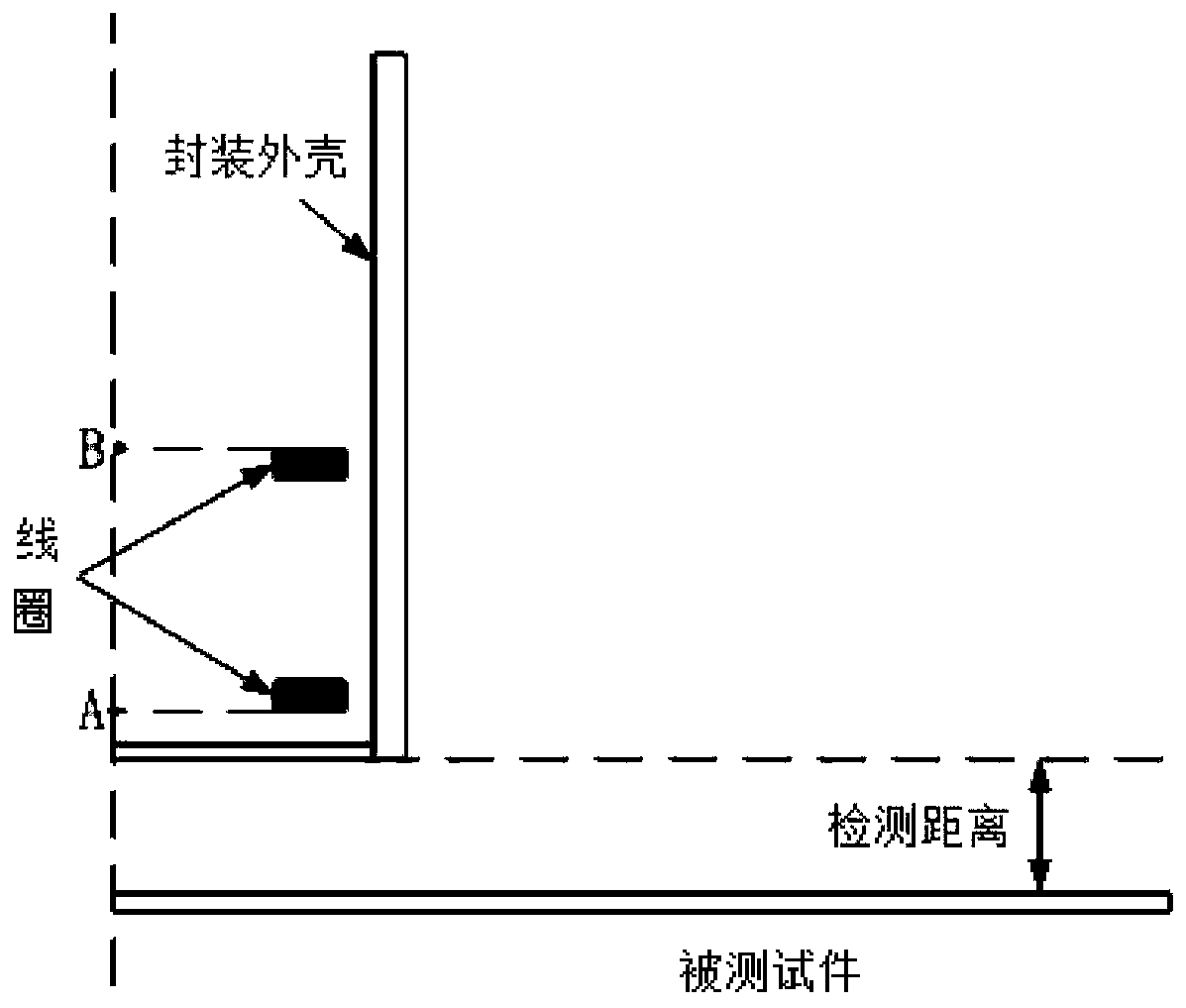
[0048] The all-metal eddy current position sensor adopts the nationally recognized food-grade metal SUS304 stainless steel to package the double-coil structure with the same parameters placed side by side, such as figure 1 As shown, the packaged probe coil is connected to the subsequent processing circuit through wires.

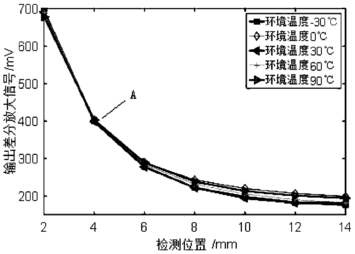
[0049] The all-metal eddy current position sensor to be processed has an excitation frequency range of 0-10kHz, a compensation temperature range of -30-90°C, and a position measurement range of 0-16mm.
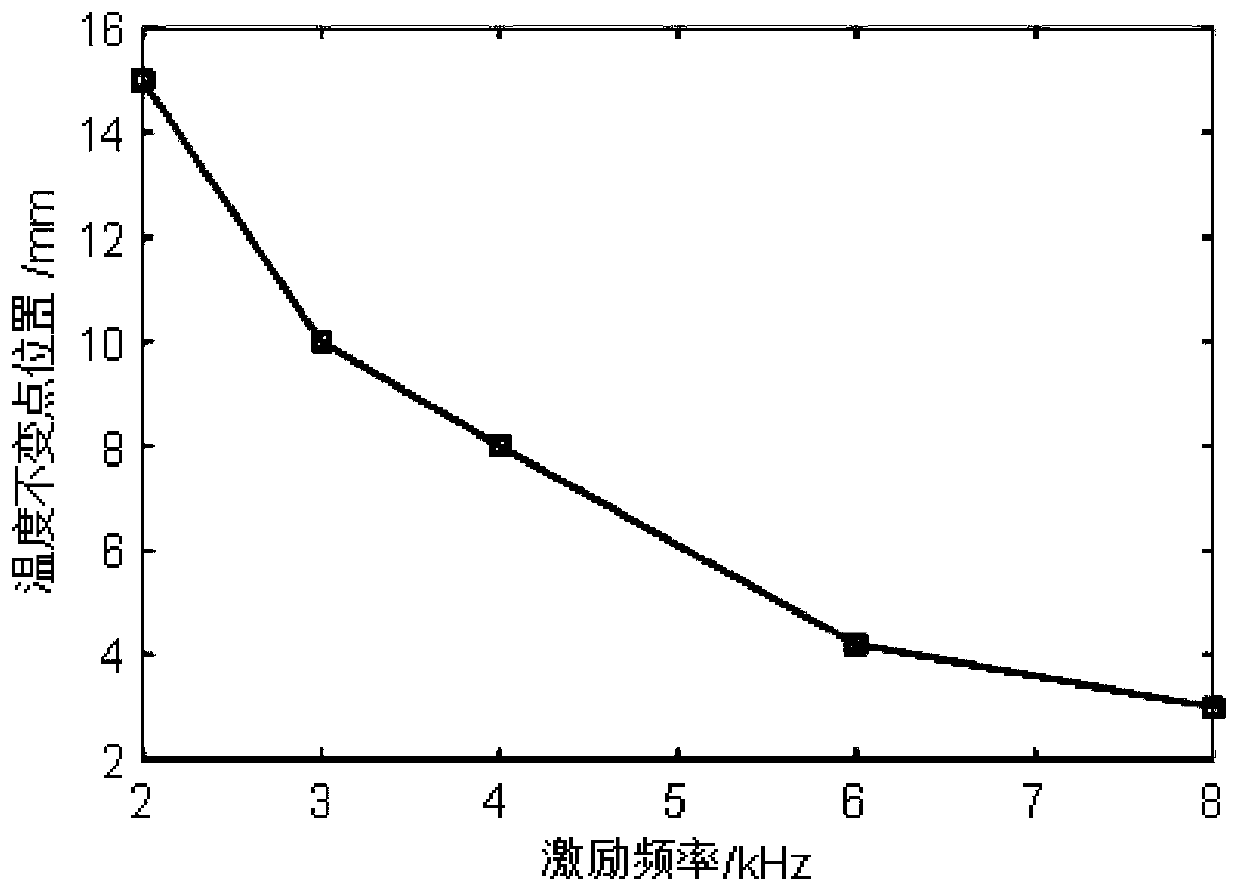
[0050] Select the typical values ​​of 2kHz, 3kHz, 4kHz, 6kHz, 8kHz within the excitation frequency range, P=5, select the typical values ​​of -30°C, 0°C, 30°C, 60°C and 90°C within the compensation tem...


PUM


Abstract

The invention provides an all-metal eddy current position sensor and a method for solving temperature drift. An eddy current position sensor is usually used as a proximity switch. When a tested objectmoves to the proximity switch and approaches a certain target detection position, the proximity switch operates. The precision of the proximity switch crucially depends on the precision of temperature drift at the target detection position, and a study finds that an output signal does not drift with the change of a temperature when an excitation frequency and position are constant, which is a temperature invariant point. According to the target detection position, by using temperature invariant point characteristics, the excitation frequency f is found, a circuit module is adjusted, and a sinusoidal signal of the excitation frequency f is generated to provide accurate excitation for two coils. According to the method, the temperature invariant point characteristics are used, the method for solving temperature drift of the all-metal eddy current position sensor is provided, thus the sensor is not affected by the change of an ambient temperature, and a detection result is accurate.

Description

technical field [0001] The invention relates to the field of measurement and control of an eddy current position sensor, in particular to an all-metal eddy current position sensor and a solution to temperature drift. Background technique [0002] Eddy current position detection technology is a non-destructive detection method based on the principle of electromagnetic induction, which is suitable for position detection of various conductive specimens. When the excitation signal is passed into the probe, the excitation magnetic field generated by the inner coil of the probe and the eddy current magnetic field induced in the tested object will be coupled, and the relative position signal between the probe and the measured object will be converted into the change of the induction coil signal. Corresponding position signals can be obtained through subsequent processing circuits. [0003] In the actual application process, the eddy current position sensor is greatly affected by t...

Claims


Application Information

Patent Timeline
Patent Type & Authority Patents(China)
IPC IPC(8): G01B7/00
Inventor 许永童
Owner SHANGHAI LANBAO SENSING TECH
Features
  • R&D
  • Intellectual Property
  • Life Sciences
  • Materials
  • Tech Scout
  • Unparalleled Data Quality
  • Higher Quality Content
  • 60% Fewer Hallucinations
Learn More