Apparatus for detecting rotary part

A technology of rotating parts and detection devices, applied in measuring devices, converting sensor output, instruments, etc., can solve the problems of computer counter rotating structure not rotating to the designated position, casualties, mechanical impact, etc., to prevent secondary mechanical impact or Injury and casualty accidents, avoid incorrect or incomplete station rotation, improve production efficiency and the effect of qualified product rate

Pending Publication Date: 2018-01-05
沃瑞克数控机床(上海)有限公司
View PDF0 Cites 2 Cited by
  • Summary
  • Abstract
  • Description
  • Claims
  • Application Information

AI Technical Summary

Problems solved by technology

[0002] There is no inspection device for the existing rotating mechanism, and it is positioned solely by computer memory or cam rotation. If the proximity sensor switch is wrong, the machine malfunctions, or the computer counter fails, the rotating structure will not rotate to the specified position. The occurrence of confusion will lead to serious mechanical impact, equipment damage and even casualties

Method used


Image

  • Apparatus for detecting rotary part
  • Apparatus for detecting rotary part

Examples


Embodiment Construction

[0014] In order to make the content of the present invention clearer and easier to understand, the content of the present invention will be further described below in conjunction with the accompanying drawings. Of course, the present invention is not limited to this specific embodiment, and general replacements known to those skilled in the art are also covered within the protection scope of the present invention. Secondly, the present invention is described in detail by means of schematic diagrams. When describing the examples of the present invention in detail, for the convenience of explanation, the schematic diagrams are not partially enlarged according to the general scale, which should not be used as a limitation of the present invention.

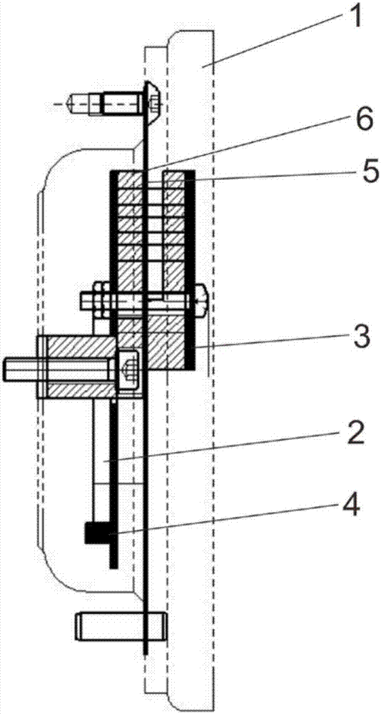
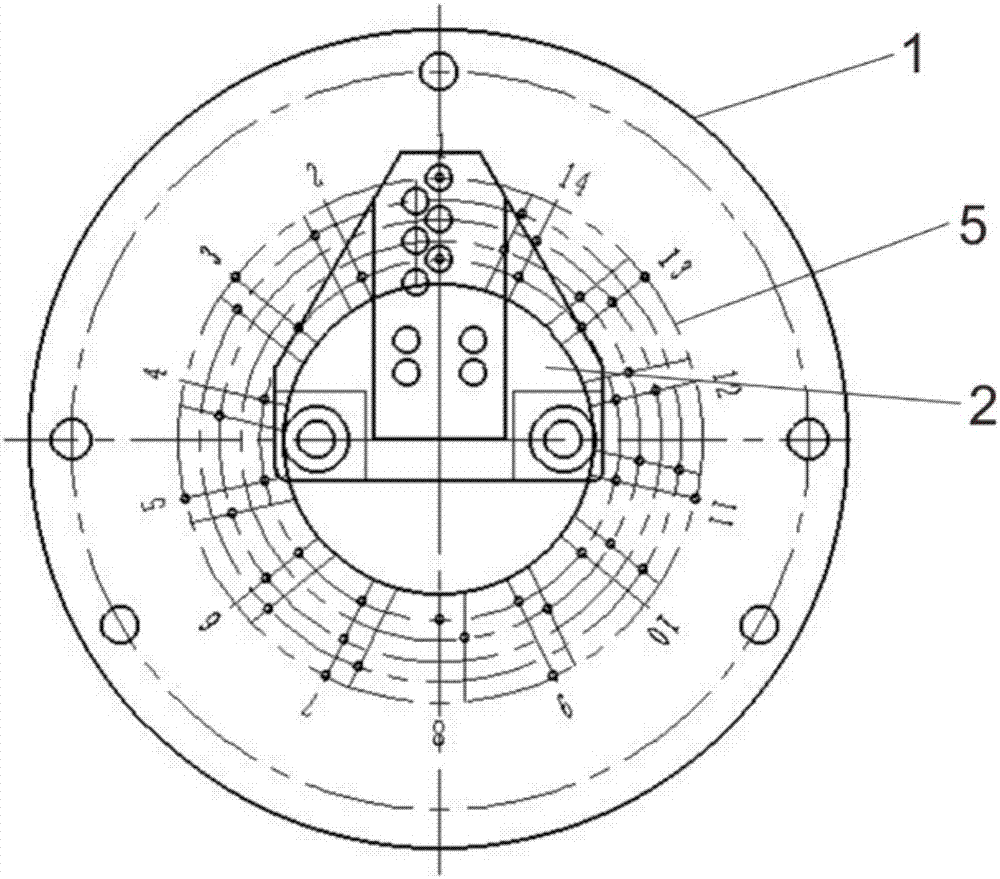
[0015] The above and other technical features and beneficial effects will be described in detail with reference to the embodiments and accompanying drawings of the detection device for rotating components of the present invention. fig...


PUM


Abstract

The invention relates to a detection device for a rotating part, which includes a casing, a rotating part, a photoelectric sensor transmitting part, a photoelectric sensor receiving part, an encoding disc, a filter plate, a decoding device and a control unit, and the rotating part is provided with a photoelectric sensor The receiving part is equipped with a photoelectric sensor emitting part, a code disc, a filter plate, a decoding device and a control unit in the housing. There are 14 stations on the code disc, and each station is composed of 4 holes in different positions. The code disc and The filter plate is installed between the photoelectric sensor emitting part and the photoelectric sensor receiving part. The present invention effectively avoids the situation that the station rotation is incorrect or not in place due to the error of the proximity sensor switch or the mechanical malfunction or the failure of the computer counter, and prevents the secondary mechanical impact or casualties caused by the incorrect station accidents, effectively helping enterprises reduce maintenance expenses, improve production efficiency and qualified product rate.

Description

technical field [0001] The invention relates to a detection device, in particular to a detection device for a rotating component. Background technique [0002] There is no inspection device for the existing rotating mechanism, and it is positioned solely by computer memory or cam rotation. If the proximity sensor switch is wrong, the machine malfunctions, or the computer counter fails, the rotating structure will not rotate to the specified position. The occurrence of confusion will lead to serious mechanical impact, equipment damage and even casualties. In view of the above defects, those skilled in the art urgently need to provide a detection device for a rotating component, which can accurately detect whether the rotating component rotates to a specified position. Contents of the invention [0003] The object of the present invention is to provide a detection device for a rotating component, which can accurately detect whether the rotating component rotates to a specif...

Claims


Application Information

Patent Timeline
Patent Type & Authority Applications(China)
IPC IPC(8): G01D5/347G01D5/249
Inventor 翟江
Owner 沃瑞克数控机床(上海)有限公司
Why Eureka
Try Eureka