
Method for measuring minute current in circuit consisting of electrified body in solution and solution

A technology for tiny currents and charged objects, applied in the direction of measuring current/voltage, measuring electrical variables, measuring devices, etc., can solve problems such as inability to measure and distinguish, difficult to measure, and difficult to measure current

Inactive Publication Date: 2018-01-05
SHENZHEN KITEWAY AUTOMATION ENG
View PDF5 Cites 2 Cited by
  • Summary
  • Abstract
  • Description
  • Claims
  • Application Information

AI Technical Summary

Problems solved by technology

[0003] However, in the prior art, since the circuit involves using water or solution as part of the conductor in the circuit, and the resistance of the non-water part is very small, the measurement of the current is very difficult
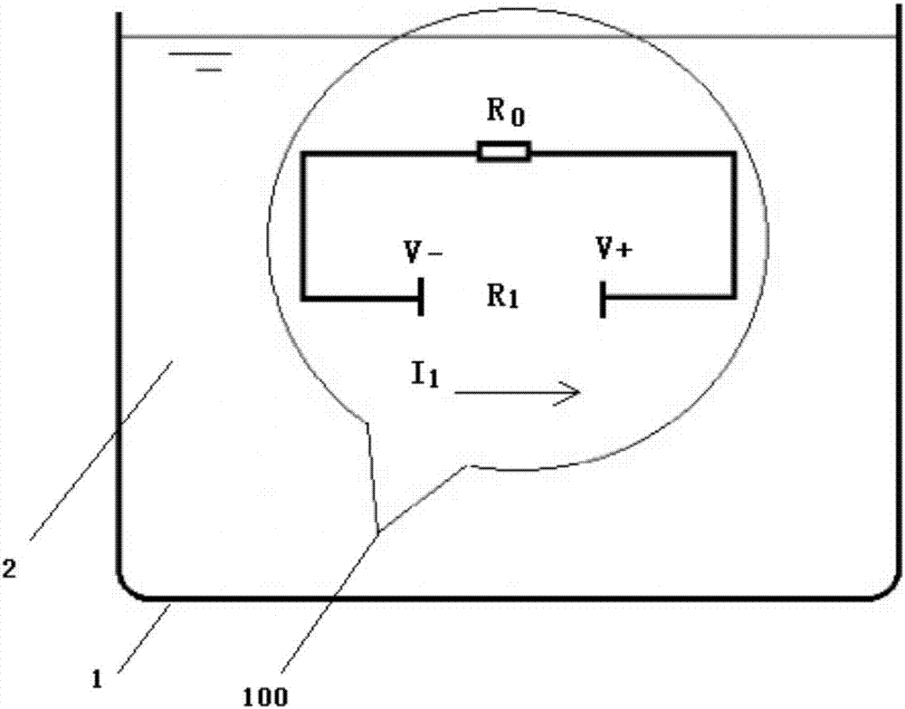
For example, in bipolar electrochemistry (Bipolar electrochemistry), the electric field is placed in water or solution, and then the single metal is placed in the electric field in the water or solution, thereby forming a potential difference on the surface of the single metal; this formed on the surface of the metal Potential difference is very small and difficult to measure
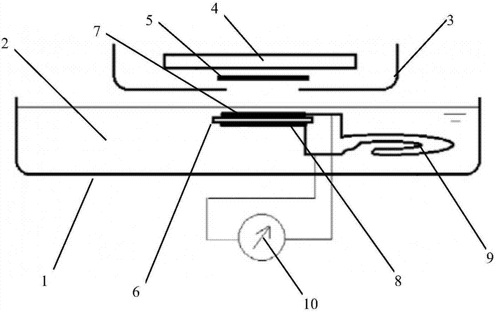
For another example, the inventor is applying for a patent for the electric potential difference phenomenon on the surface of a single metal induced by ultraviolet rays. When judging whether there is a potential difference, the general measurement method cannot be measured and judged.

Method used


Image

  • Method for measuring minute current in circuit consisting of electrified body in solution and solution
  • Method for measuring minute current in circuit consisting of electrified body in solution and solution
  • Method for measuring minute current in circuit consisting of electrified body in solution and solution

Examples


Embodiment Construction

[0021] The specific embodiments of the present invention will be further described below in conjunction with the accompanying drawings. It should be noted here that the descriptions of these embodiments are used to help understand the present invention, but are not intended to limit the present invention. In addition, the technical features involved in the various embodiments of the present invention described below may be combined with each other as long as they do not constitute a conflict with each other.

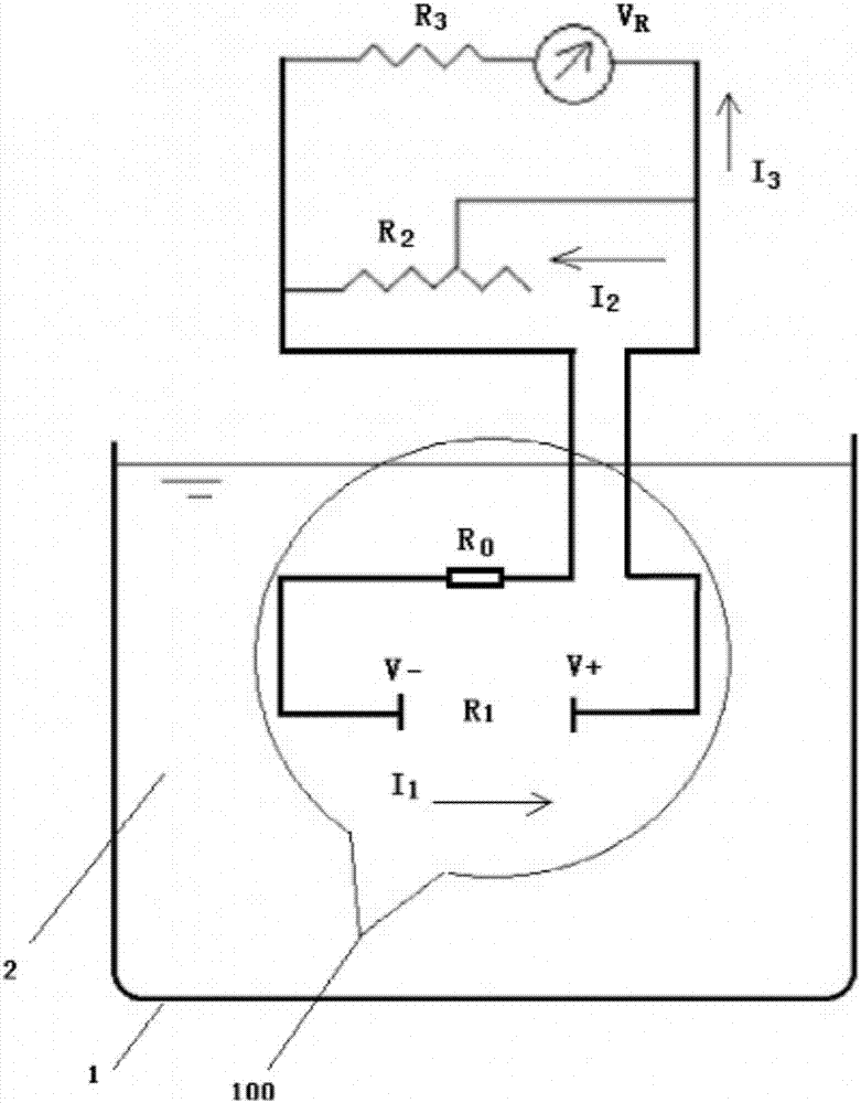
[0022] A method for measuring tiny currents in charged bodies in solution, comprising the steps of:

[0023] S1. Connect a variable resistor in series in the measured circuit to form a measurement circuit;

[0024] S2. Connect a voltmeter in parallel to the variable resistor to obtain the voltage value at both ends of the variable resistor;

[0025] S3. Obtain the microcurrent value on the charged body according to the calculation formula, the calculation formula is as...


PUM


Abstract

The invention discloses a method for measuring minute current in a circuit consisting of an electrified body in a solution and the solution The method for measuring minute current in a circuit consisting of an electrified body in the solution and the solution comprises steps of connecting a variable resistor or a metal wire which can be used as a variable resistor to a measured circuit in series and connecting a voltmeter to the variable resistor or the metal wire which can be used as the variable resistor in parallel, obtaining voltage values on two ends of the variable resistor wire, obtaining a minute current value on the electrified body according to a calculation formula, wherein the calculation formula is as follow: I1=VR / R2, wherein I1 is a value of minute current on the electrifiedbody, VR is a voltage value of the variable resistor or on two ends of the metal wire which can be used as the variable resistor, and R2 is a resistance value of the variable resistor or the metal wire which can be used as a variable resistor. The method for measuring the minute current in the circuit consisting of the electrified body in the solution and the solution can measure the minute current formed by minute potential differences of the electrified body in the water.

Description

technical field [0001] The invention relates to the technical field of micro-current measurement, in particular to a method for measuring micro-current in a loop composed of a charged body in a solution and a solution. Background technique [0002] In technology research and development, it is often necessary to measure some very small electrical signals, for example, under certain physical and chemical conditions, measure a very small (microampere) current passing through a very low resistance conductor, or even just to judge whether there is electricity or not. signal generated. On the other hand, in actual production, it is also necessary to use sensors to measure some tiny electrical signals. [0003] However, in the prior art, since the circuit involves using water or solution as part of the conductor in the circuit, and the resistance of the non-water part is very small, the measurement of the current is very difficult. For example, in bipolar electrochemistry (Bipol...

Claims


Application Information

Patent Timeline
IPC IPC(8): G01R19/00
Inventor 张连峰张金松宛如意威廉.A.安德森
Owner SHENZHEN KITEWAY AUTOMATION ENG
Learn More