
Automobile yaw stability control method based on gain scheduling

A control method and yaw stabilization technology, applied in adaptive control, general control system, control/regulation system, etc., can solve the problem that the yaw rate of the vehicle cannot track its reference value, etc., and achieve the effect of excellent self-adaptability

Inactive Publication Date: 2018-01-05
HARBIN INST OF TECH
View PDF4 Cites 3 Cited by
  • Summary
  • Abstract
  • Description
  • Claims
  • Application Information

AI Technical Summary

Problems solved by technology

[0004] The purpose of the present invention is to solve the problem that the yaw rate of the vehicle cannot track its reference value in the case of perturbation of the relevant parameters in the existing fixed-parameter vehicle yaw stability control, and proposes a vehicle yaw stability control based on gain scheduling. Pendulum Stability Control Method

Method used


Image

  • Automobile yaw stability control method based on gain scheduling
  • Automobile yaw stability control method based on gain scheduling
  • Automobile yaw stability control method based on gain scheduling

Examples


specific Embodiment approach 1

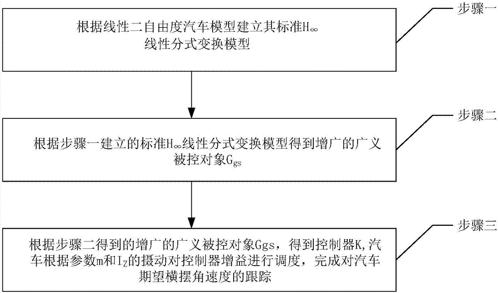
[0030] Specific implementation mode one: as figure 1 As shown, a vehicle yaw stability control method based on gain scheduling includes the following steps:

[0031] Step 1: Establish a standard based on a linear two-degree-of-freedom vehicle model The linear fraction transformation model is:

[0032]

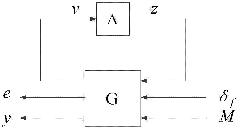
[0033] Where e is the tracking error, y is the measurement output, F u (G, Δ) is the upper linear fractional transformation of G and Δ, G is the generalized controlled object, Δ is the independently separated parameter uncertainty multiplier, δ f is the front wheel rotation angle, M is the yaw moment input;

[0034]

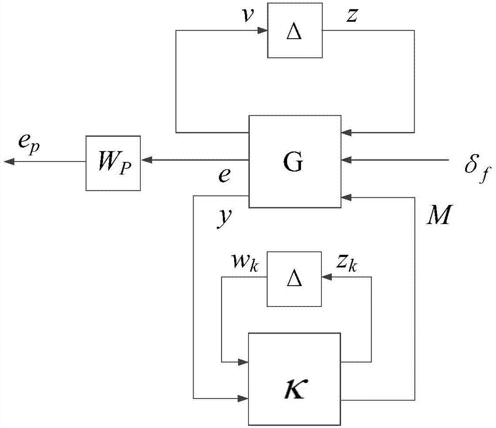
[0035] Step 2: Based on the criteria established in Step 1 The augmented generalized plant G obtained from the linear fraction transformation model gs (G gs Add input (w k ,z k ) and output (w k ,z k ) augmented generalized accused object);

[0036] Step 3: The augmented generalized controlled object G obtained from Step 2 gs , to obtain the co...

specific Embodiment approach 2

[0038] Specific embodiment 2: The difference between this embodiment and specific embodiment 1 is that in the step 1, the standard is established according to the linear two-degree-of-freedom automobile model The specific process of linear fraction transformation model is as follows:

[0039] Such as figure 2 As shown, considering the two-degree-of-freedom vehicle model of the vehicle's lateral motion and yaw motion, the dynamic state equation of the vehicle is:

[0040]

[0041] in

[0042] β is the sideslip angle of the center of mass, γ is the yaw rate, is the first derivative of β, is the first derivative of γ, δ f is the front wheel rotation angle, M is the yaw moment input, I z is the vehicle yaw moment of inertia, c αf and c αr are the cornering stiffness of the front and rear wheels respectively, u is the longitudinal speed of the vehicle, a is the distance from the center of mass to the front axle, b is the distance from the center of mass to the rea...

specific Embodiment approach 3

[0056] Specific embodiment three: the difference between this embodiment and specific embodiment one or two is: the parameter perturbation model is expressed as:

[0057] m=m 0 +ξ 1 W m

[0058] I z =I 0 +ξ 2 W I

[0059] where |ξ 1 |≤1, |ξ 2 |≤1.

[0060] Other steps and parameters are the same as those in Embodiment 1 or Embodiment 2.


PUM


Abstract

The invention relates to an automobile yaw stability control method based on gain scheduling and aims to solve the problem that a reference value of automobile yaw angle speed cannot be traced by adopting an existing parameter-fixed automobile yaw stability control method under the situation that relevant parameters are perturbed. The automobile yaw stability control method comprises the steps that a standard (shown in the description) linear fractional transformation model is established according to a linear two-freedom-degree automobile model; 2, an augmented general controlled object Ggs is obtained according to the standard (shown in the description) linear fractional transformation model established in the step 1; 3, according to the augmented general controlled object Ggs obtained in the step 2, a controller K is obtained, the gain of the controller K of an automobile is dispatched according to the disturbances of whole automobile mass m and rotational inertia IZ, and expected automobile yaw angle speed tracing is completed. The automobile yaw stability control method is used in the field of linear control.

Description

technical field [0001] The invention relates to the field of linear control, in particular to a vehicle yaw stability control method based on gain scheduling. Background technique [0002] During the turning process of the car, there will be understeer, which will cause the car to fail to complete the desired steering operation according to the driver's intention; more dangerously, there will be oversteer, which will cause the car to lose stability, spin sharply and skid or roll over. This dangerous condition will cause great damage to the vehicle and the driver, so it is necessary to control the lateral yaw stability of the vehicle so that the vehicle can work under a moderate understeer condition. [0003] Most of the current vehicle yaw stability control is designed under the nominal parameters, and the obtained controller has a good control effect when the parameters are fixed. However, during the operation of the car, many parameters will change, for example, the mass ...

Claims


Application Information

Patent Timeline
Patent Type & Authority Applications(China)
IPC IPC(8): G05B13/04
Inventor 孙维超张晋华
Owner HARBIN INST OF TECH
Learn More