Novel smart city system

A smart and urban technology, applied in transmission systems, instruments, electrical components, etc., can solve problems such as difficulty in improving environmental quality, achieve the effects of avoiding traffic congestion, realizing controllable utilization, and excellent air quality

Inactive Publication Date: 2018-01-05
上海鹿釜科技发展有限公司
View PDF0 Cites 2 Cited by
  • Summary
  • Abstract
  • Description
  • Claims
  • Application Information

AI Technical Summary

Problems solved by technology

[0004] The technical problem to be solved by the present invention is to provide a new type of smart city system, which can solve the technical problems in the prior art that the various parts of the city system are relatively independent and the environmental quality is difficult to improve

Method used


Image

  • Novel smart city system
  • Novel smart city system
  • Novel smart city system

Examples


Embodiment 1

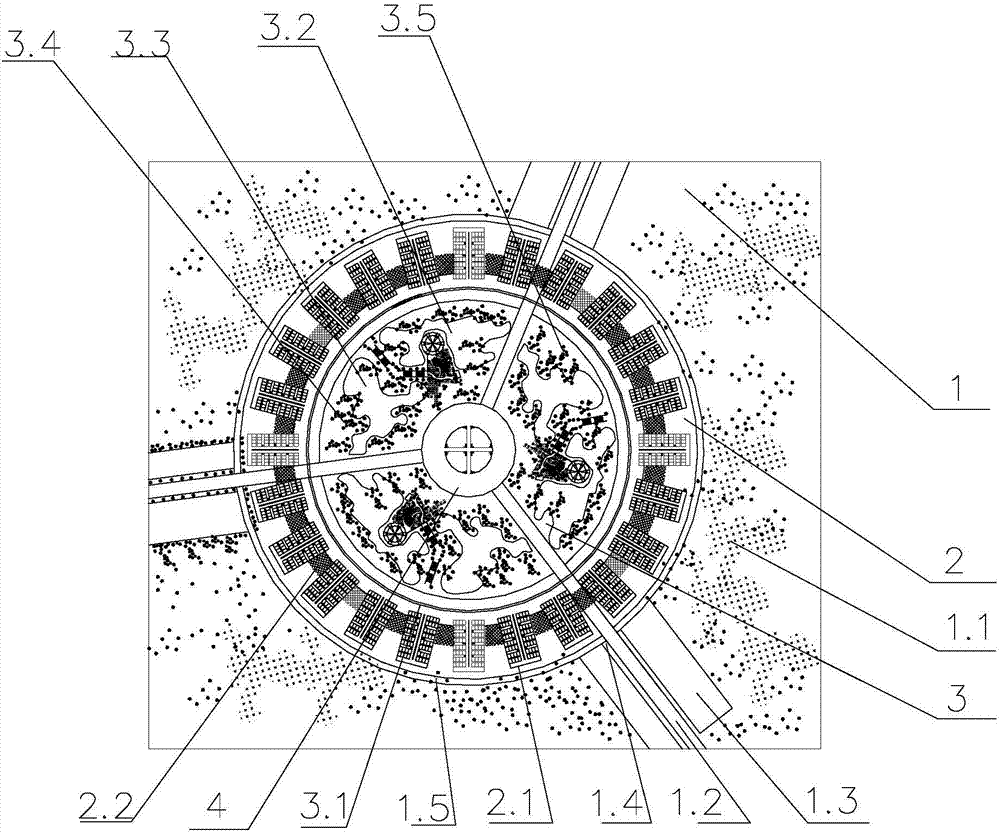
[0038] A new type of smart city system, including from the outside to the inside:

[0039] Greening module 1 is used to isolate the smart city system from the outside world and provide fresh air to the smart city system;

[0040] City module 2, providing residence or office space;

[0041] Living community module 3, for residents in the smart city system to have leisure and entertainment;

[0042] Island Module 4;

[0043] The greening module includes a green belt 1.1 and three main roads 1.2 connecting the urban area module 2 with the outside world. With the island module 4 as the center, the three main roads 1.2 are distributed at different angles. Residents can enter the urban area module 2 through these three main roads 1.2 . There are parking lots 1.3 on both sides of the main road entering the city 1.2, and the parking lots 1.3 on both sides of the main road entering the city 1.2 are to prevent fuel vehicles from entering the urban module 2 and ensure the air quality ...

Embodiment approach

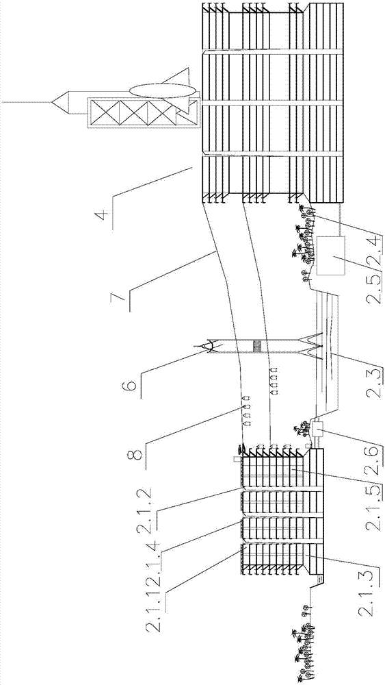
[0049]In this embodiment, the high-rise building 2.1.1 adopts a movable building exterior wall 2.1.5, and a solar energy collecting panel is arranged on the movable building exterior wall. When the sun is sufficient, the residents can push the movable building exterior wall 2.1.5 to the outside, and the solar collection panels collect after being irradiated by sunlight, and convert the collected solar energy into electric energy for the residents; In snowy weather, residents can push the movable building exterior wall 2.1.5 to the inside, so as to prevent the solar energy collection panel from being affected by bad weather and shorten its service life. This kind of movable building exterior wall 2.1.5 can be intelligently controlled or artificially controlled. In this embodiment, the movable building exterior wall 2.1.5 is electrically controlled. The electric control system is matched with the mobile terminal, and if the mobile terminal has a weather forecast APP, the electr...


PUM


Abstract

The invention discloses a new type of smart city system, which respectively includes from outside to inside: a greening module, an urban area module, a living community module, and an island module; the greening module includes a green belt and at least one main road connecting the urban area module with the outside world; The module includes several high-rise areas, and air purification devices are installed between adjacent high-rise areas, and several high-rise areas are surrounded by arcs; the living community module is located inside the ring city, including the ring traffic arterial road around the ring city, for the smart city system. There are entertainment venues, living squares, several crop belts, and several green belts for residents to have leisure and entertainment; the island module interacts with the city module through several cableways, and residents in the smart city system can transition from the high-rise area to the island module through cableway transportation. The smart city system described in the present invention has excellent air quality, convenient transportation, abundant water and electricity, and creates high-quality living conditions for residents.

Description

technical field [0001] The invention relates to the technical field of urban planning, in particular to a novel smart city system. Background technique [0002] At present, with the acceleration of urbanization and the rapid growth of population, the problem of urban environmental pollution is becoming more and more serious; coupled with the exponential growth of transportation vehicles, a large number of transportation vehicles and unreasonable urban construction lead to urban traffic congestion. In addition, fuel transportation Exhaust emissions from tools lead to a serious decline in urban environmental quality. Therefore, how to build an urban system with a good ecological environment and reasonable configuration has always been a research topic for urban construction workers. [0003] The diversity of the existing urban system is poor, that is, in terms of form and appearance, the interior of the city is more of a simple combination, and its internal parts cannot coope...

Claims


Application Information

Patent Timeline
IPC IPC(8): H04L29/08G06Q50/02G06Q50/06G06Q50/08
Inventor 许强
Owner 上海鹿釜科技发展有限公司
Why Eureka
Try Eureka