Continuous automatic assembly machine of lug plate elastic piece

An automatic assembly machine and ear plate technology, applied in metal processing, metal processing equipment, manufacturing tools, etc., can solve the problems of deformation of the inclined part of the shrapnel, difficulty in automatic processing, and low processing accuracy, so as to avoid elastic deformation and structural design The effect of ingenious, continuous automatic processing

Active Publication Date: 2018-01-09
CHONGQING TECH & BUSINESS UNIV
View PDF5 Cites 10 Cited by
  • Summary
  • Abstract
  • Description
  • Claims
  • Application Information

AI Technical Summary

Problems solved by technology

[0002] Most of the ear plates are used as connectors, and their structures are multi-purpose, and most of them are non-standard parts, some such as Figure 12 As shown, it consists of a horizontal plate and a vertical plate. The width of the horizontal plate is larger than that of the vertical plate, and the upper part of the horizontal plate is provided with a shrapnel mounting post for installing the shrapnel. The lower part of the shrapnel mounting post will be provided with a positioning hole concentric with it, and the used Shrapnel such as Figure 13 As shown, it is a non-standard shrapnel with multiple planes, slopes and curved surfaces. Most of the processing of this type of product is done manually, and it is difficult to realize automatic processing. Even if it is assembled by manual pressing, it will cause damage to the inclined part of the shrapnel. Certain deformation, low processing efficiency, and low processing accuracy, so it is urgent to design a continuous automatic assembly of non-standard ear plates and non-standard shrapnel to improve assembly efficiency.

Method used


Image

  • Continuous automatic assembly machine of lug plate elastic piece
  • Continuous automatic assembly machine of lug plate elastic piece
  • Continuous automatic assembly machine of lug plate elastic piece

Examples


Embodiment Construction

[0040] In order to enable those skilled in the art to better understand the technical solution of the present invention, the present invention will be described in detail below in conjunction with the accompanying drawings. The description in this part is only exemplary and explanatory, and should not have any limiting effect on the protection scope of the present invention. .

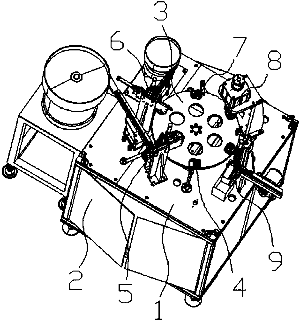
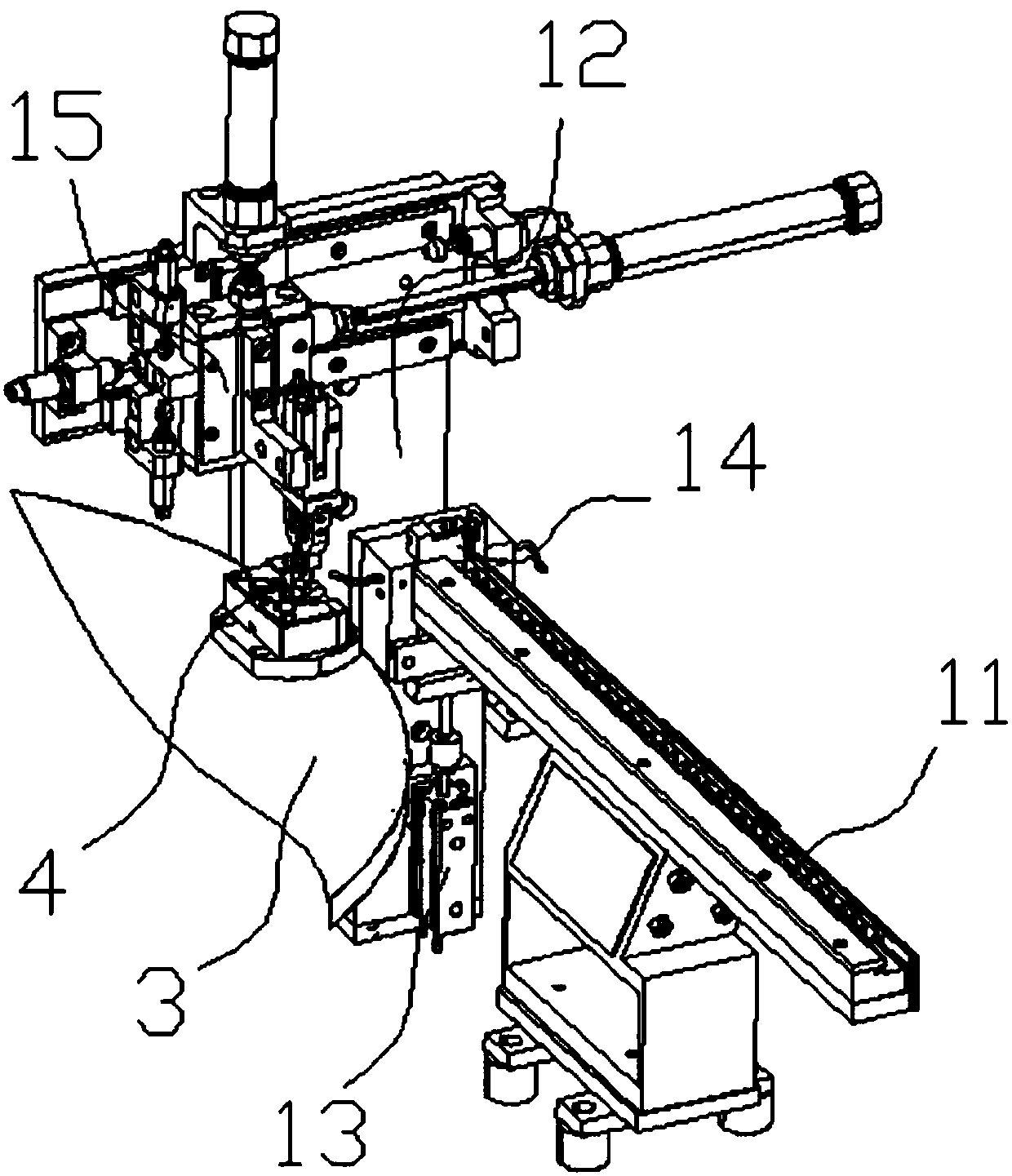
[0041] Such as Figure 1-Figure 14 As shown, the specific structure of the present invention is: a continuous automatic assembly machine for lug shrapnel, which includes a frame 1 and a power distribution control box 2. The frame 1 is provided with a turntable drive device and a turntable that cooperate with each other. 3. The turntable 3 is evenly provided with carriers 4, and the frame 1 is sequentially provided with lug plate feeding mechanisms 5 and shrapnel tops that cooperate with the carriers 4 on the turntable 3 along the rotation direction of the turntable 3. material mechanism 6, press-fit m...


PUM


Abstract

The invention relates to a continuous automatic assembly machine of a lug plate elastic piece. The continuous automatic assembly machine comprises a rack, a power distribution control box, a rotary disc and carriers. A lug plate feeding mechanism, an elastic piece feeding mechanism, a press-fitting mechanism and a discharging mechanism are arranged on the rack. Each carrier comprises a carried material mounting seat embedded into the rotary disc. A carried material seat lifting block penetrating the rotary disc is arranged in each carried material mounting seat. A vertical carried material seat composite spring is arranged between each carried material seat lifting block and the lower portion of the corresponding carried material mounting seat. A carried material seat cooperating with a product is arranged above each carried material seat lifting block. A press-fitting device comprises a press-down device cooperating with the products on the carriers and a carried material seat jackingdevice which is located below the press-down device and cooperates with the carried material seat lifting blocks. According to the continuous automatic assembly machine, the carried material seat lifting blocks and the press-down device can be in butt joint precisely, meanwhile, pressing assembly of a lock piece and a lug plate can be achieved, it can be ensured that the press-down portion is a flat plate between two elastic piece mounting columns, the press-fitting precision is ensured, elastic deformation of the elastic pieces is avoided, and meanwhile continuous automatic machining is achieved.

Description

technical field [0001] The invention relates to the field of automatic processing equipment, in particular to a continuous automatic assembly machine for lug shrapnel. Background technique [0002] Most of the ear plates are used as connectors, and their structures are multi-purpose, and most of them are non-standard parts, some such as Figure 12 As shown, it consists of a horizontal plate and a vertical plate. The width of the horizontal plate is larger than that of the vertical plate, and the upper part of the horizontal plate is provided with a shrapnel mounting post for installing the shrapnel. The lower part of the shrapnel mounting post will be provided with a positioning hole concentric with it, and the used Shrapnel such as Figure 13 As shown, it is a non-standard shrapnel with multiple planes, slopes and curved surfaces. Most of the processing of this type of product is done manually, and it is difficult to realize automatic processing. Even if it is assembled by ...

Claims


Application Information

Patent Timeline
Patent Type & Authority Applications(China)
IPC IPC(8): B23P19/027
Inventor 喻其炳王晓丹何塞杨帅余婷梃
Owner CHONGQING TECH & BUSINESS UNIV
Why Eureka
Try Eureka