Chamfering and grinding device for disc-cutting edge

A technology of disc shearing and chamfering, which is applied in the direction of grinding drive device, grinding workpiece support, grinding machine tool parts, etc. Problems such as short service life and high labor intensity of workers can achieve the effects of improving utilization rate and production efficiency, reducing processing costs, and simplifying assembly and debugging

Active Publication Date: 2018-01-09
ANSHAN FALAN STEEL STRIP CO LTD
View PDF8 Cites 0 Cited by
  • Summary
  • Abstract
  • Description
  • Claims
  • Application Information

AI Technical Summary

Problems solved by technology

Neither the surface grinder nor the cylindrical grinder can effectively chamfer the corners of the disc shears.
Since the surface grinder and the cylindrical grinder can only grind the end face and the outer circle of the cutting blade, the disc cutting blade produced in this way has a short service life, frequent replacement, high labor intensity for workers, and low production efficiency.

Method used


Image

  • Chamfering and grinding device for disc-cutting edge
  • Chamfering and grinding device for disc-cutting edge

Examples


Embodiment Construction

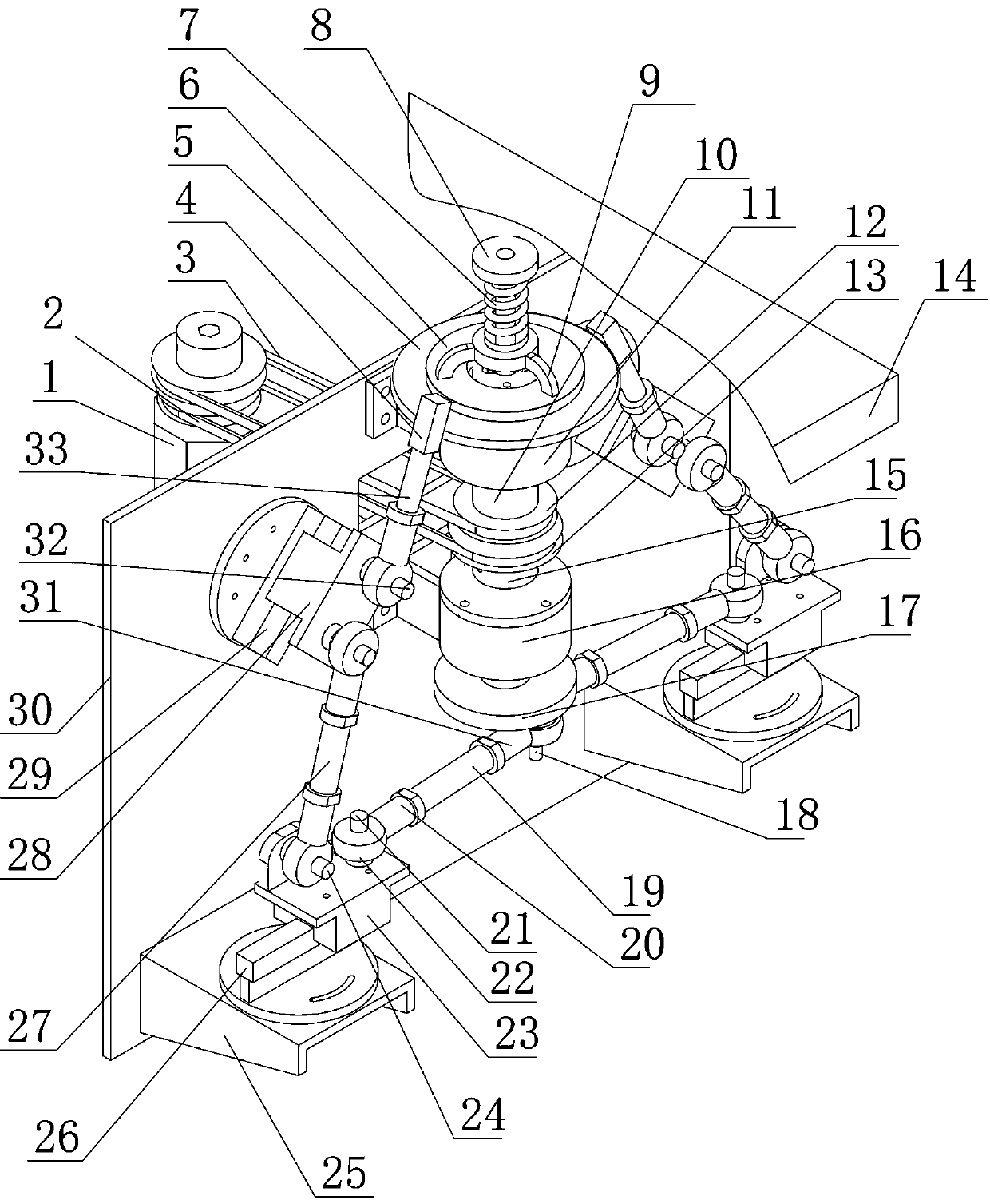
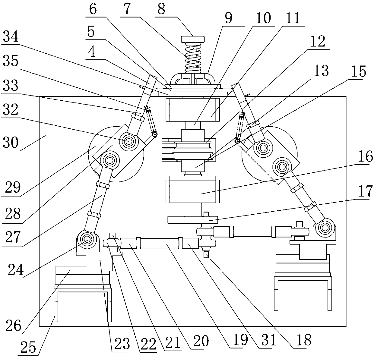
[0017] Such as figure 1 , 2 , as shown, the disc shear edge chamfering grinding device of the present invention includes a support stand 14, a support stand 30 fixed below the support stand, and a driving device on one side of the support stand is arranged here The rotary motion transmission device of the cutting blade and the reciprocating linear motion transmission device of the grinding head on the other side of the supporting vertical plate are connected with the driving device, so The above-mentioned shearing blade rotary motion transmission device is composed of the upper transmission wheel 12 connected to the driving device, the upper transmission shaft 10 fixedly connected with this upper transmission wheel, and the shearing blade tray 34 fixedly connected with this upper transmission shaft, passing through The upper transmission shaft is arranged on the cutting edge piece 5 above the cutting edge tray, and the gland assembly that fixes the cutting edge piece on the c...


PUM


Abstract

The invention belongs to the technical field of cold-rolled strip manufacturing tool, and particularly relates to a chamfering and grinding device for a disc-cutting edge. The chamfering and grindingdevice comprises a support platform, a support vertical plate, a driving device, a cutting edge piece rotation motion transmission device and a grinding head reciprocating linear motion transmission device, wherein the cutting edge piece rotation motion transmission device comprises an upper transmission wheel, an upper transmission shaft, a cutting edge tray, a cutting edge piece, a pressure cover component and an upper bearing component; the grinding head reciprocating linear motion transmission device comprises a lower transmission wheel, a lower transmission shaft, a sliding block rotatingdisc, an eccentric shaft, a connecting rod transmission mechanism I, a connecting rod transmission mechanism II and a lower bearing component; and each of the connecting rod transmission mechanism Iand the connecting rod transmission mechanism II is connected with the cutting edge piece. According to the chamfering and grinding device for the disc-cutting edge, the two types of motion, namely the rotation motion and the linear motion are realized by adopting the same driving device, all the components adopt an adjustable assembling method, the design and the structure are simple, the assembly and debugging are simple and easy, the requirement on the manufacturing precision is not too high, the processing difficulty and cost of the equipment are reduced, and the utilization ratio and production efficiency of the equipment are improved.

Description

technical field [0001] The invention belongs to the technical field of cold-rolled steel strip manufacturing tools, and in particular relates to a chamfering grinding device for disc shear blades. Background technique [0002] In the production process of cold-rolled steel strip and packaging steel strip, the steel strip generally has to go through the process of feeding-uncoiling-longitudinal shearing and slitting. The cutting edge slitting machine is used to complete, that is, after the steel strip is fed-uncoiled, it enters the slitting machine for cutting and slitting of the steel strip, and then enters the next process flow. In the process of cutting and slitting, the disc shears used will also be subject to great wear and tear. When the disc shears are worn to a certain extent, they need to be re-grinded. For use again, the traditional shearing blade grinding method has two grinding methods: plane grinding and cylindrical grinding. The grinding of the end face of the ...

Claims


Application Information

Patent Timeline
Patent Type & Authority Applications(China)
IPC IPC(8): B24B3/46B24B3/00B24B41/06B24B47/12B24B47/16
Inventor 王恩栋齐保峰钟丽君鲁茜谷安任李万福高伟
Owner ANSHAN FALAN STEEL STRIP CO LTD
Why Eureka
Try Eureka