Wheel device of multifunctional carrying vehicle

A carrier car and multi-functional technology, which is applied in the field of wheels, can solve the problems of long-distance cargo transport, difficulty in transporting upstairs, and long time-consuming, and achieve the effects of less energy consumption, convenient transport of goods, and cost savings

Inactive Publication Date: 2018-01-09
重庆雷步特科技有限责任公司
View PDF5 Cites 2 Cited by
  • Summary
  • Abstract
  • Description
  • Claims
  • Application Information

AI Technical Summary

Problems solved by technology

[0004] The technical problem to be solved by the present invention is that couriers deliver the couriers one by one to the customer's home, and the transportation distance of the goods is long, and it is difficult to carry them upstairs. Difficult, time-consuming problems

Method used


Image

  • Wheel device of multifunctional carrying vehicle

Examples


Embodiment 1

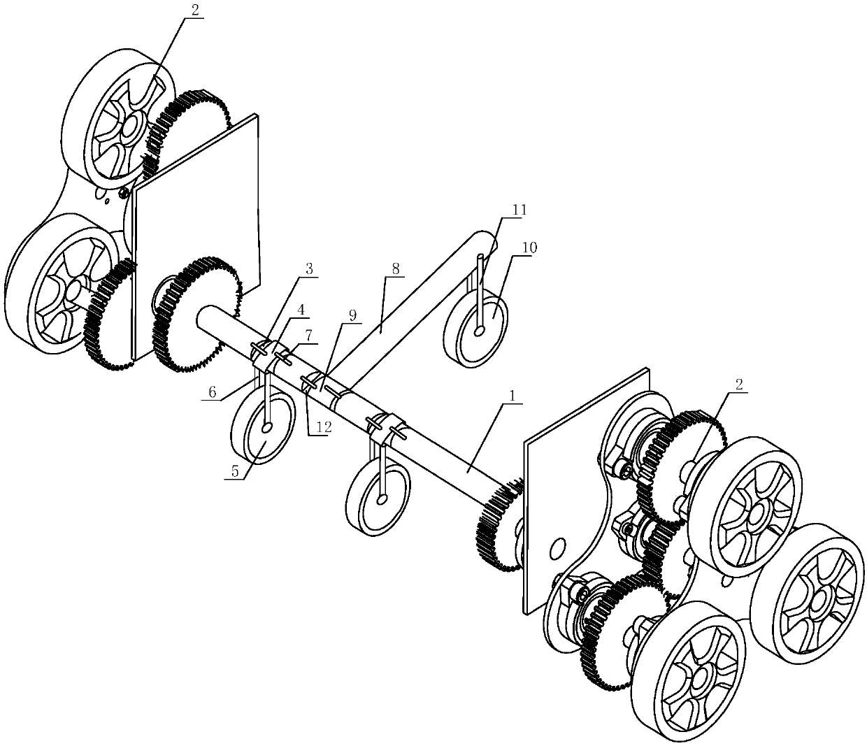
[0022] Such as figure 1 As shown, the wheel device of a multifunctional carrier trolley of the present invention includes a main shaft 1 and a three-star wheel set 2 arranged at both ends of the main shaft 1. At least two annular grooves 3 are arranged on the main shaft 1, and each annular groove 3 A collar 4 is provided, and the collar 4 is set on the main shaft 1. The collar 4 rotates around the main shaft 1 in the annular groove 3. The collar 4 is connected with a driving wheel 5, and the rolling direction of the driving wheel 5 is the same as that of the Samsung The three-star wheels in the wheel set 2 have the same rolling direction, and the running wheel 5 and the collar 4 are connected by a telescopic rod 6, and the collar 4 is hinged with at least two connecting rods 7 connected and fixed to the main shaft 1 on both sides of the annular groove 3 , one end of the connecting rod 7 is hinged with the collar 4 and rotates around the hinged end, and the other end of the con...

Embodiment 2

[0025] Based on Embodiment 1, the main shaft 1 is provided with two annular grooves 3, the two annular grooves 3 are symmetrical about the radial bisector of the main shaft 1, and the main shaft 1 between the two annular grooves 3 is connected with a horizontal The center axis of the balance bar 8 is perpendicular to the center axis of the main shaft 1, and one end of the balance bar 8 is rotationally connected with the main shaft 1 through the ring 9, the ring 9 is set on the main shaft 1, and the other end of the balance bar 8 is connected with a Balance wheel 10, the direction of motion of balance wheel 10 is identical with running wheel 5, and the both sides of balance wheel 10 is connected with balance bar 8 by telescopic rotating bar 11, and balance wheel 10 turns up and down around balance bar 8. The main shaft 1 is provided with an annular limiting groove 12 for installing the ring 9 . The ring 9 is equipped with fixing devices that are movably connected with the main ...


PUM


Abstract

The invention discloses a wheel device of a multifunctional carrying vehicle. The wheel device comprises a main shaft and three-star wheel sets arranged at the two ends of the main shaft, two or moreannular grooves are formed in the main shaft, a sleeve ring is arranged inside each annular groove, the main shaft is sleeved with the sleeve rings, the sleeve rings rotate around the main shaft inside the grooves and are connected with traveling wheels, the rolling direction of the traveling wheels is the same as that of three-star wheels in the three-star wheel sets, the traveling wheels are connected with the sleeve rings through telescopic rods, two or more connecting rods are hinged to the sleeve rings, connected with the parts, on the two sides of each annular groove, of the main shaft,and fixed to the parts, on the two sides of each annular groove, of the main shaft, one end of each connecting rod is hinged to the corresponding sleeve ring and rotates around the hinged end, and theother ends of the connecting rods are movably connected with the main shaft. By adjusting the positions of the traveling wheels, ascending and descending of the three-star wheels are achieved, levelrod traveling and stair climbing of the carrying vehicle are easier, goods are convenient to transport for express workers, and the problem that the transportation time for the goods is long is solved.

Description

technical field [0001] The invention relates to a wheel, in particular to a wheel device of a multifunctional carrying trolley. Background technique [0002] With the development of science and technology, the scientific and technological content of products has increased. A large number of products of high-tech enterprises are small in size and light in weight, but their value is high, which takes up a lot of working capital. Express transportation can deliver these products to customers as soon as possible, and Provide good packaging, warehousing, customs declaration and logistics services to meet the needs of enterprises and realize the greatest possible social division of labor. [0003] Express delivery speed is one of the important indicators for evaluating the service quality of express companies. At present, customers will request express delivery to their homes, which increases the distance of goods transportation and increases the workload of couriers, and couriers...

Claims


Application Information

Patent Timeline
Patent Type & Authority Applications(China)
IPC IPC(8): B62D57/024
Inventor 伍国果金容蒋家兴王勇
Owner 重庆雷步特科技有限责任公司
Why Eureka
Try Eureka