A new type of crane slider device

A sliding block and crane technology, which is applied in the directions of transportation and packaging, load hanging components, cleaning methods and utensils, etc., can solve the problem of poor contact between the sliding block and the sliding line, the maintenance difficulty of the sliding line and the sliding block, and reduce the operation of the crane. rate and other issues, to achieve the effect of good comprehensive use performance, less maintenance time, and improved power supply stability

Active Publication Date: 2019-11-12
XINXING DUCTILE IRON PIPES CO LTD
View PDF7 Cites 0 Cited by
  • Summary
  • Abstract
  • Description
  • Claims
  • Application Information

AI Technical Summary

Problems solved by technology

[0003] The sliders of the currently used cranes, especially the sliders of large cranes, are iron sliders. The iron sliders are in contact with the upper iron slide wires for conductive power supply. The following problems often occur in this power supply method: 1. The site environment is relatively poor. In the worst case, the upper part of the sliding line is seriously dusty, which is likely to cause poor contact between the sliding block and the sliding line, and intermittent power failure; 2. The slider is large in size, and it is difficult to replace it after serious wear; 3. When the sliding line is not on the same level When it is up, the wear parts of the slider are relatively concentrated, causing local wear and causing difficulties in the maintenance of the sliding line and the slider
In the maintenance process of the crane, the slider needs to be replaced again, and the replacement time is usually more than one hour. Frequent replacement of the slider of the crane not only increases the workload of the electrician but also reduces the operation rate of the crane

Method used


Image

  • A new type of crane slider device
  • A new type of crane slider device
  • A new type of crane slider device

Examples


Embodiment 1

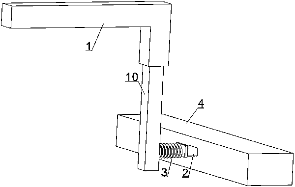
[0030] The novel crown block slider device of the present invention includes a bracket 1, a slider fixing frame and a slider 2, and the specific structure is as follows figure 1 shown. Wherein the slider 2 is arranged on the slider fixing frame, and the slider fixing frame is fixedly connected with the bracket 1, and the bracket 1 is fixedly arranged on one side of the crane, and the bracket provides support for the slider fixing frame. The slider 2 is in contact with the side of the slide wire 4 to take power, and the slider 2 slides along the side of the slide wire 4 . One side of slide block 2 fits and contacts with the side of slide wire 4 and the opposite side is fixedly connected with hold-down spring-3, and the other end of hold-down spring-3 is fixedly connected with slide block holder, so that hold-down spring-1 Under the action of 3, the slider 2 is compressed to fit closely with the slide wire 4. In this embodiment, the slider fixing frame can directly use the con...

Embodiment 2

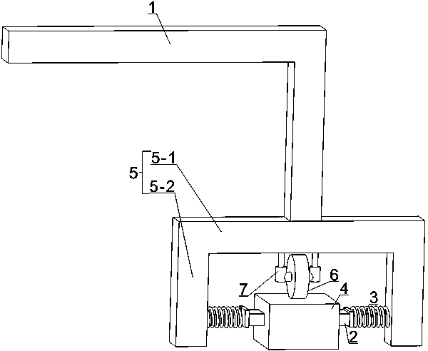
[0033] This embodiment is improved on the basis of Embodiment 1, and the main improvement lies in the improvement of the slider fixing frame. In this embodiment, the slider fixing frame is an inverted U-shaped bracket 5, and the U-shaped bracket 5 includes two vertical beams and a cross beam 5-1 integrally formed, wherein the cross beam 5-1 is located above the slide wire 4, The two vertical beams 5-2 are located on both sides of the slide line 4, the U-shaped support 5 surrounds the three sides of the slide line 4, and the beam 5-1 of the U-shaped support 5 is connected with the support 5. In this embodiment, two sliders 2 are set, and the two sliders 2 are symmetrically arranged on both sides of the slide line 4, and one end of the slider 2 is connected to the vertical beam 5- The other end of the inner side of 2 is in contact with the side of slide wire 4 . That is, a slide block 2 is arranged on the inner side of the two vertical beams 5-2, and the two slide blocks 2 are ...

Embodiment 3

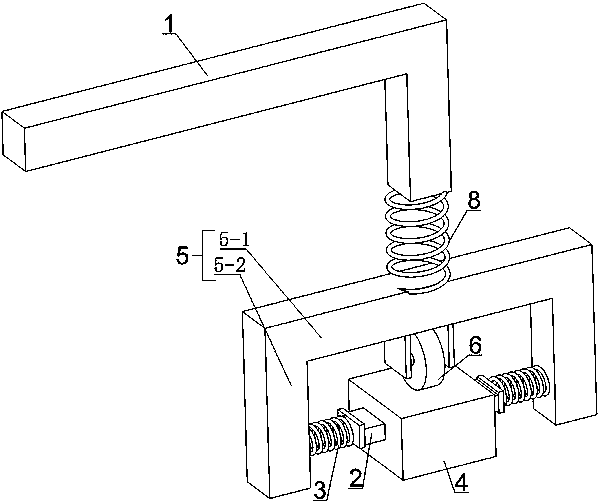
[0038] This embodiment is modified on the basis of Embodiment 2, and the modification lies in the connection method between the U-shaped bracket and the bracket. In this embodiment, the U-shaped bracket 5 and the bracket 1 are connected by a compression spring 2 8, and a pressure wheel 6 is set at the middle of the lower end surface of the crossbeam 5-1 of the U-shaped bracket 5. Adjust the position of the U-shaped support by adjusting the compression spring 2 8 to ensure that the device is not subject to partial wear of the slide block due to incorrect slide lines. For specific adjustment, it is advisable for the slider 2 to be located in the middle of the side of the slide wire 4, while ensuring that the pressure roller 6 is located on the upper end surface of the slide wire 6. The distance between compression spring two 8 and the connection point of crossbeam 5-1 and crossbeam 5-1 two ends is the same, that is, the connection point of compression spring two 8 and crossbeam ...


PUM


Abstract

The invention relates to a novel crown block sliding block device, and belongs to the technical field of crown block equipment. The novel crown block sliding block device comprises a support fixed toone side of a crown block, a sliding block fixing frame connected with the support, and a sliding block arranged on the sliding block fixing frame. One end of the sliding block makes contact with theside face of a sliding wire, and the other end of the sliding block is connected with the sliding block fixing frame through a pressing spring. The contact face of the sliding block and the sliding wire is arranged on the side face of the sliding wire, crown block outage caused by bad sliding wire and sliding block contact due to the severe environment and excessive dust is avoided in the device,and normal running of the crown block is guaranteed. Through the arrangement of the pressing spring, the sliding block and the sliding wire are in non-rigidity contact, abrasion between the sliding block and the sliding wire is reduced, the service life of the device is prolonged, and the repairing and maintaining time is shortened. The novel crown block sliding block device is simple in structure, stable in running, good in performance and easy to repair and maintain; and normal running of the crown block can be guaranteed, it is guaranteed that production is normally conducted, and the comprehensive using performance is good.

Description

technical field [0001] The invention relates to a novel crane slider device, which belongs to the technical field of crane equipment. Background technique [0002] The crane is an important equipment in industrial production. It is efficient and convenient to use the crane to transfer materials. The crane is driven by a motor and runs along the track. A slider is set on the crane, and the slider slides on the slide line for power-taking operation. Therefore, normal contact and power supply between the slider and the slide line is an important condition for the normal operation of the crane. [0003] The sliders of the currently used cranes, especially the sliders of large cranes, are iron sliders. The iron sliders are in contact with the upper iron slide wires for conductive power supply. The following problems often occur in this power supply method: 1. The site environment is relatively poor. In the worst case, the upper part of the sliding line is seriously dusty, which ...

Claims


Application Information

Patent Timeline
Patent Type & Authority Patents(China)
IPC IPC(8): B66C13/12B08B1/02B08B1/00
Inventor 黎晓阳牛永生车蕾
Owner XINXING DUCTILE IRON PIPES CO LTD
Why Eureka
Try Eureka