
A Centrifugal Gas Compressor Desuperheater with Central Nozzle Structure

A technology of gas compressors and central nozzles, which is applied in the direction of machines/engines, liquid fuel engines, mechanical equipment, etc., can solve the problems of inability to effectively reach the cooling mainstream, insufficient liquid cooling evaporation time, and large impact of cooling liquid droplets, etc., to achieve Avoid impact water erosion, improve the effect, increase the effect of evaporation time

Active Publication Date: 2019-03-26
BEIHANG UNIV
View PDF6 Cites 2 Cited by
  • Summary
  • Abstract
  • Description
  • Claims
  • Application Information

AI Technical Summary

Problems solved by technology

[0006] The present invention provides a centrifugal gas compressor desuperheater with a central nozzle structure that overcomes the above problems or at least partially solves the above problems, which solves the problem of insufficient liquid cooling evaporation time and the inability to effectively reach the cooling mainstream in the prior art , and the impact of cooling liquid droplets is relatively large, causing the compressor blades to be easily damaged

Method used


Image

  • A Centrifugal Gas Compressor Desuperheater with Central Nozzle Structure
  • A Centrifugal Gas Compressor Desuperheater with Central Nozzle Structure

Examples


specific Embodiment approach

[0019] DETAILED DESCRIPTION OF THE PREFERRED EMBODIMENTS The specific implementations of the present invention will be further described in detail below in conjunction with the drawings and embodiments. The following examples are used to illustrate the present invention, but are not intended to limit the scope of the present invention.

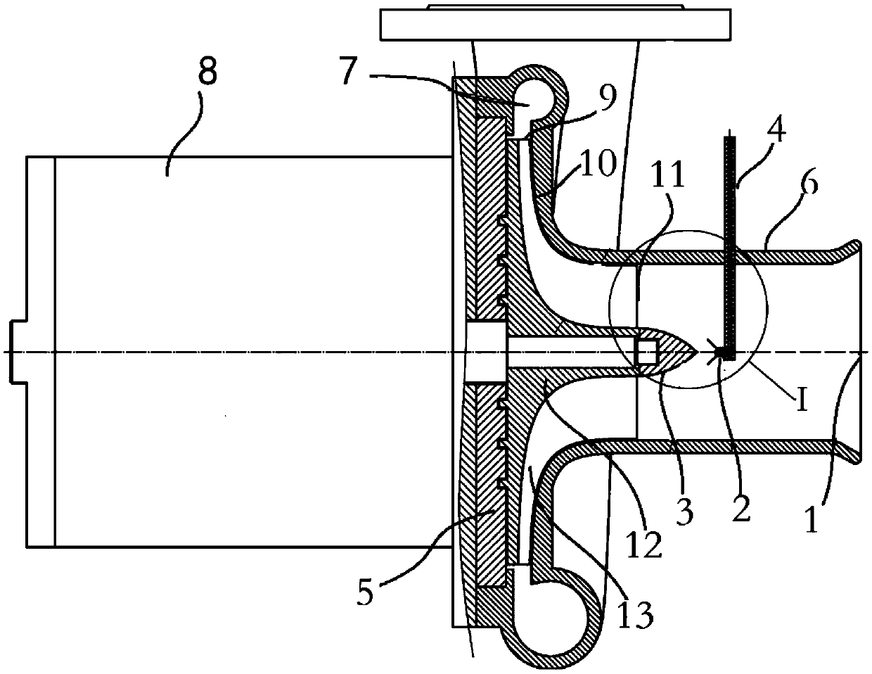
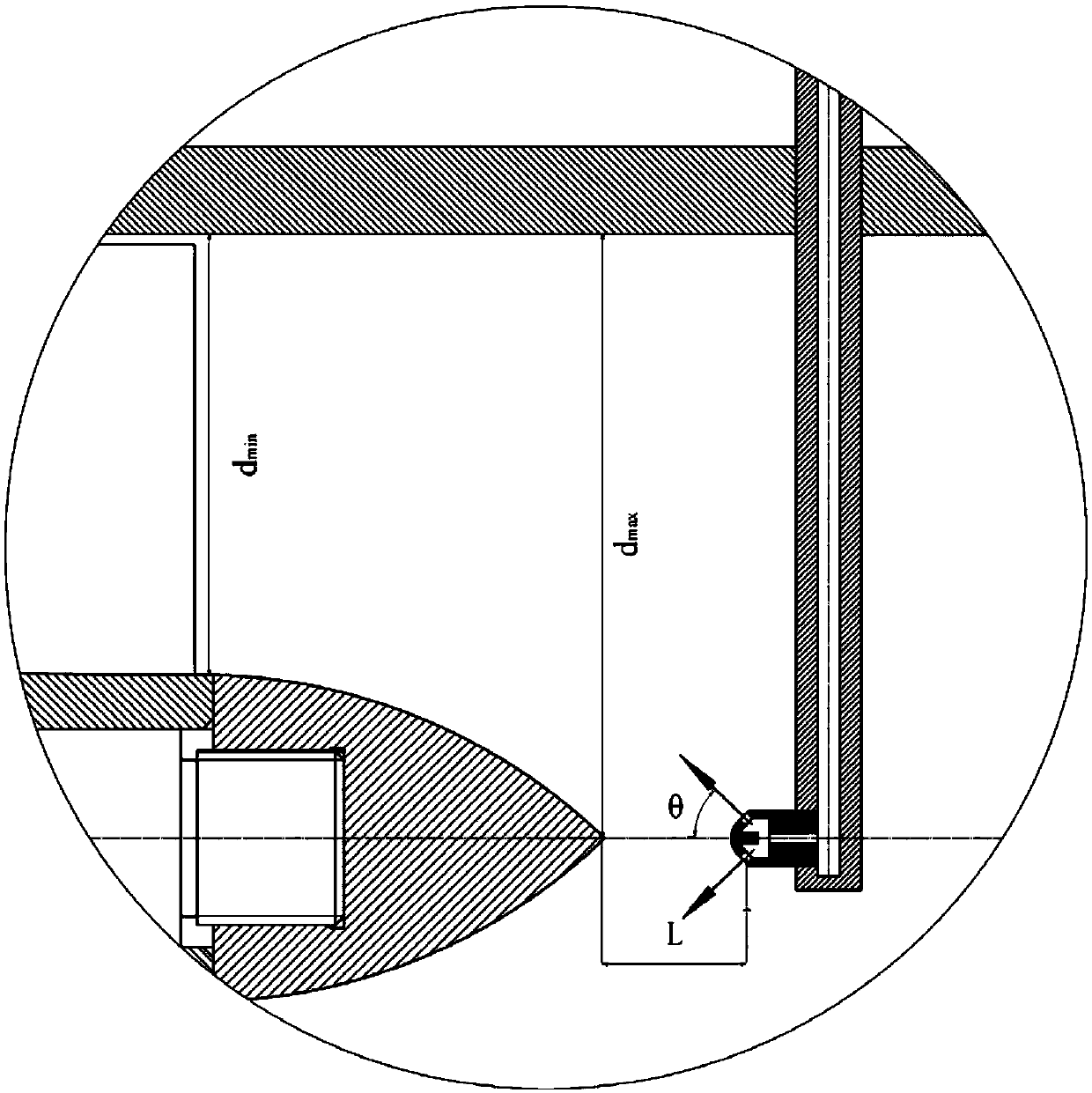
[0020] Such as figure 1 As shown in the figure, a gas compressor desuperheater with a central nozzle structure is shown, the gas compressor includes a compressor casing 6, and the compressor casing 6 includes an opening to the direction of the compressor rotation axis The air inlet 1 and the air inlet passage connected to the air inlet also include a compressor impeller 5, which is rotatably supported in the compressor housing 6 around the rotation axis of the rotating shaft , the rotating shaft is driven by a high-speed motor 8, and the side of the compressor impeller 5 close to the gas compressor inlet 1 is provided with a diversion cone 3 ...


PUM


Abstract

The invention provides a centrifugal gas compressor desuperheater with a center nozzle structure. A centrifugal gas compressor comprises a compressor shell; and the compressor shell comprises an intake port opened to the direction of a compressor rotating shaft, and an intake channel connected with the intake port. The centrifugal gas compressor further comprises a compressor impeller; the compressor impeller is rotationally supported in the compressor shell with the rotating axis of the rotating shaft as center, and is used for compressing gas flowing in from the intake port; a guide cone isarranged on the side, near the intake port, of the compressor impeller; a desuperheater nozzle is arranged in the intake channel from the guide cone to the intake port, and is used for spraying cooling liquid to the guide cone; and through setting of the angle of spraying liquid by the desuperheater nozzle, the liquid sprayed by the desuperheater nozzle is sucked into the channel of the compressorimpeller through the guide cone to mix with main gas of the compressor, so that the desuperheater effect is improved, the compression power is reduced, and the compressor efficiency is improved.

Description

technical field [0001] The invention relates to the technical field of gas compressors, in particular to a centrifugal gas compressor desuperheater with a central nozzle structure. Background technique [0002] Gas compression technology such as air and water vapor has broad application prospects and great development potential in chemical industry, refrigeration industry, wastewater treatment and other fields. Mechanical steam distillation technology, superheated steam drying technology, and steam fans used in industrial engineering all involve or rely on water vapor compression technology. Studying and mastering gas compression technology can improve compression efficiency, improve system reliability and life, and bring about revolutionary changes in related fields. [0003] Under normal circumstances, the compressor only inhales gas. However, when the system is actually running, it is often due to the unstable operation of the gas-liquid separator, the liquid level of th...

Claims


Application Information

Patent Timeline
Patent Type & Authority Patents(China)
IPC IPC(8): F04D29/58
Inventor 李育隆吴宏尹浩羽
Owner BEIHANG UNIV
Learn More