Generalized filter comprehensive method
A synthesis method and filter technology, applied in the generalized synthesis field, can solve problems such as inability to realize asymmetrical frequency response, inability to arbitrarily place transmission zeros, etc.
- Summary
- Abstract
- Description
- Claims
- Application Information
AI Technical Summary
Problems solved by technology
Method used
Image
Examples
Embodiment 2
[0080] Embodiment 2 is also a third-order real coefficient bandpass filter, without loss of generality, the technical index is set as follows: the passband is located at [18, 22]MHz, and the return loss in the passband is greater than 20dB. In order to reflect the flexibility of the design method of the present invention, the two transmission zeros in Embodiment 2 are placed at zero frequency, and the other transmission zero is located at infinite frequency. According to the technical indicators, the filtering polynomial derived from formulas (13a) and (13b) is:
[0081]
[0082]
[0083]
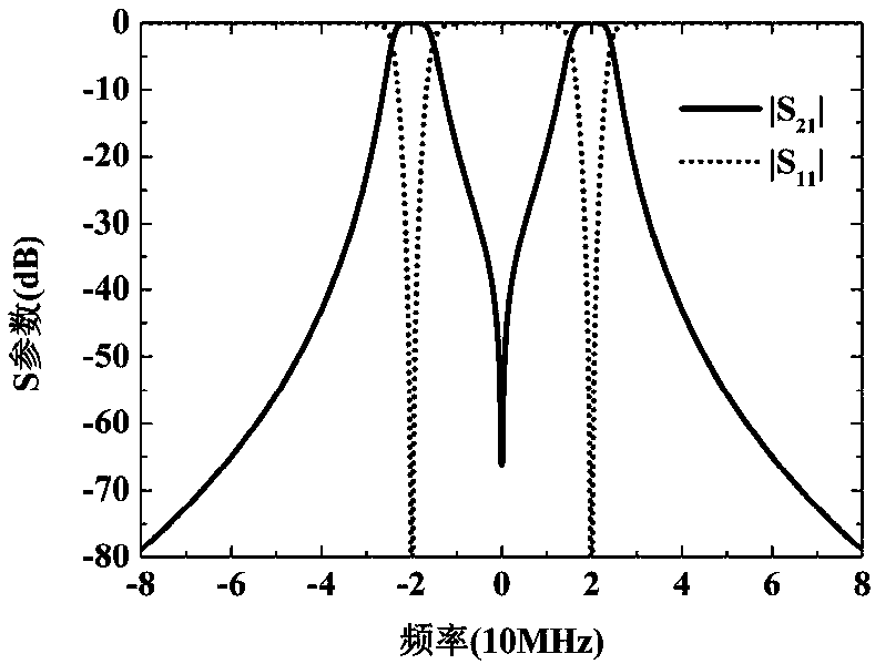
[0084] The frequency response corresponding to the filter polynomial is as follows Figure 4 As shown, it can be seen that the frequency response of the real coefficient bandpass filter is symmetrical about the zero frequency. Since the polarity of the transmission polynomial P is an even function, and the polarity of the reflection polynomial F is also an even function, Embodiment ...
Embodiment 3
[0085] The third embodiment is also a third-order real coefficient bandpass filter, without loss of generality, the technical index is set as follows: the passband is located at [18, 22]MHz, and the return loss in the passband is greater than 20dB. In order to reflect the flexibility of the design method of the present invention, the three transmission zero points in Embodiment 3 are all placed at zero frequency. According to the technical indicators, the filtering polynomial derived from formulas (13a) and (13b) is:
[0086]
[0087]
[0088]
[0089] The frequency response corresponding to the filter polynomial is as follows Figure 6 As shown, it can be seen that the frequency response of the real number bandpass filter is symmetrical about the zero frequency. Using these filtering polynomials, a lumped parameter LC circuit can be used to realize, as Figure 7 shown. Figure 7 The value of the component in: R S =R L =50Ω, L 1 =0.1729μH,L 2 =0.2358μH,L 3 =0....
Embodiment 4
[0090] Embodiment 4 is also a third-order real number bandpass filter, without loss of generality, the technical index is set as follows: the passband is located at [18, 22]MHz, and the return loss in the passband is greater than 20dB. In order to reflect the flexibility of the design method of the present invention, one transmission zero point in Embodiment 4 is placed at zero frequency, one transmission zero point is placed at a limited frequency of 30 MHz, and one transmission zero point is placed at an infinite frequency. According to the technical indicators, the filtering polynomial derived from formulas (13a) and (13b) is:
[0091]
[0092]
[0093]
[0094] The frequency response corresponding to the filter polynomial is as follows Figure 8 As shown, it can be seen that the frequency response of the real coefficient bandpass filter is symmetrical about the zero frequency. Using these filtering polynomials, a lumped parameter LC circuit can be used to realize...
PUM
 Abstract
Description
Claims
Application Information
 - R&D
- Intellectual Property
- Life Sciences
- Materials
- Tech Scout
- Unparalleled Data Quality
- Higher Quality Content
- 60% Fewer Hallucinations
Browse by: Latest US Patents, China's latest patents, Technical Efficacy Thesaurus, Application Domain, Technology Topic, Popular Technical Reports.
© 2025 PatSnap. All rights reserved.Legal|Privacy policy|Modern Slavery Act Transparency Statement|Sitemap|About US| Contact US: help@patsnap.com


