Low pass filter with embedded resonator

Active Publication Date: 2010-05-27
ALCATEL LUCENT SAS
View PDF9 Cites 19 Cited by
  • Summary
  • Abstract
  • Description
  • Claims
  • Application Information

AI Technical Summary

Benefits of technology

[0021]Accordingly, a need exists for a simply structured, easy to manufacture SIR LPF that has built-in suppression of close to pass band spurious signals. This invention and its various described exemplary embodiments are directed to this need and prov

Problems solved by technology

Realizable microwave LPFs, however, do not have such characteristics.
This has drawbacks, though, including increased cost and, particularly, pass-band insertion loss.
Further, adding a mask filter in line with a main filter may increase the complexity of the tuning procedure

Method used


Image

  • Low pass filter with embedded resonator
  • Low pass filter with embedded resonator
  • Low pass filter with embedded resonator

Examples


Embodiment Construction

[0046]Referring now to the drawings, in which like numerals refer to like components or steps, there are disclosed broad aspects of various exemplary embodiments.

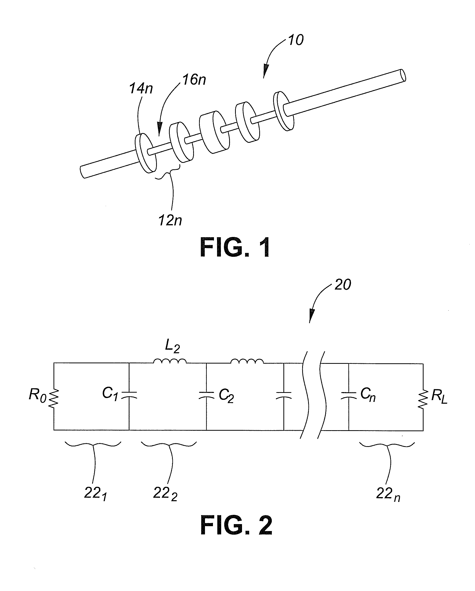
[0047]In one broad aspect, a subject of this invention is an embedded resonator that may be integrated with various filter structures such as, for example, a coaxial SIR LPF. According to aspects having an SIR LPF, the embedded notch resonator introduces finite transmission zeros to the all transmission-pole response of the coaxial low-pass filter, which significantly enhances the spurious suppression of the coaxial filter. This provides an integrated filter / notch resonator having, among other features, sharp rejection near the operating band of the system, while maintaining a wide spurious suppression window.

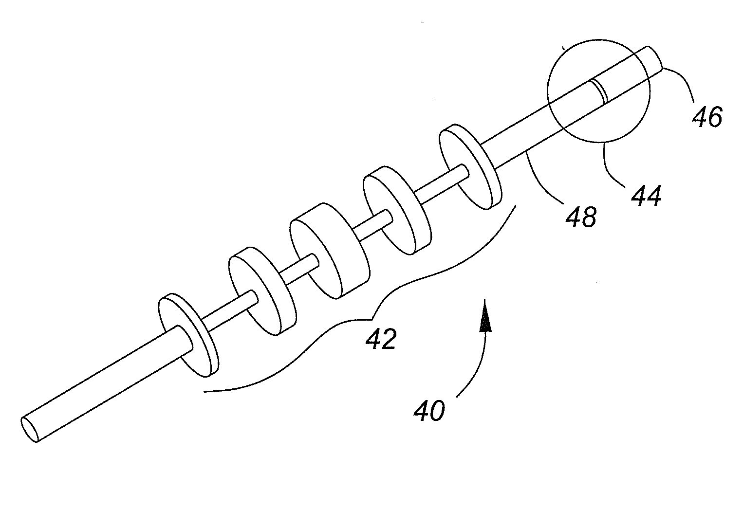
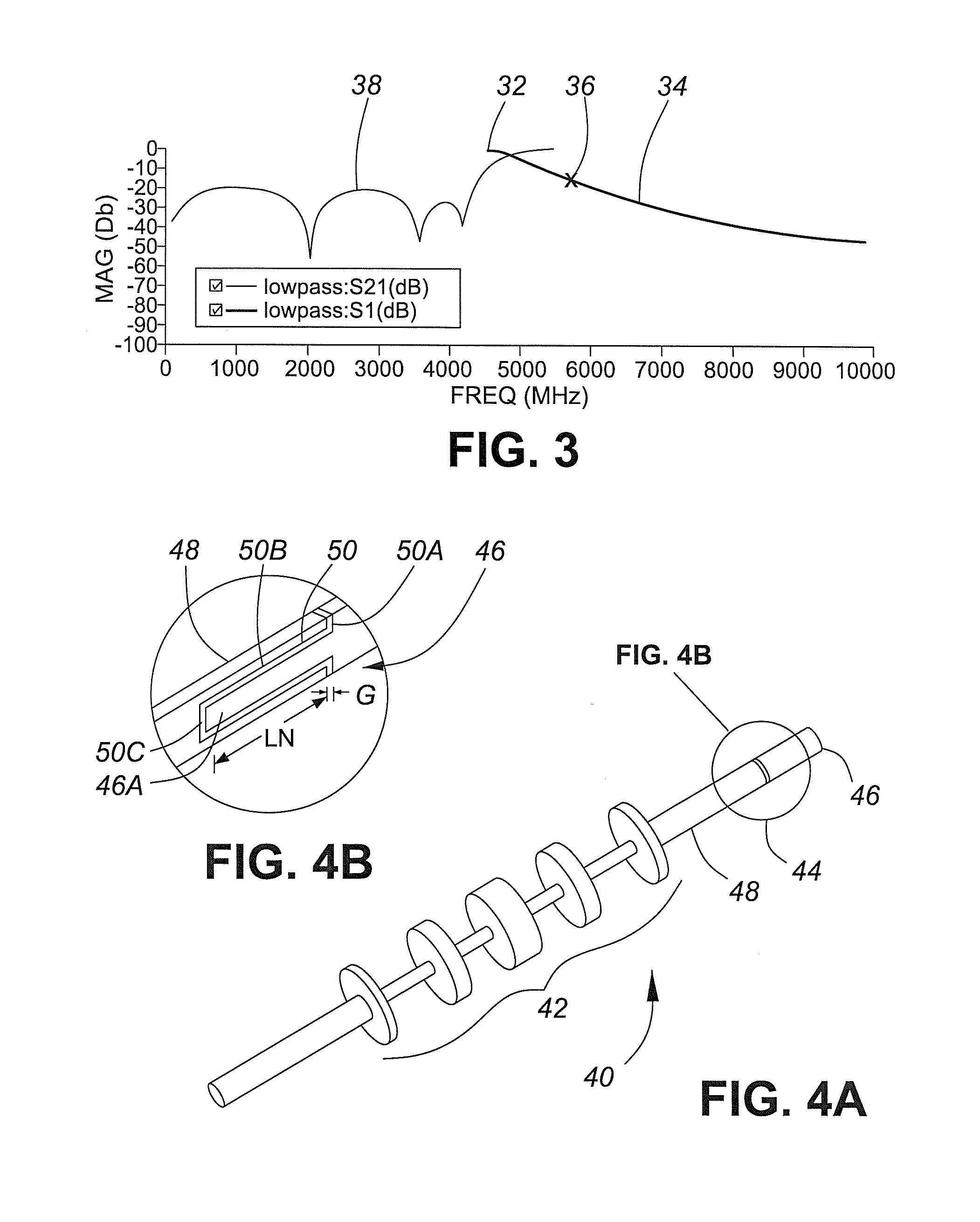
[0048]FIG. 4A is a three-dimensional depiction of one example 40 having an SIR LPF 42 with an embedded resonator having structure including a capacitive coupling at region 44, according to one embodiment. FIG. 4B is an...


PUM


Abstract

An embedded resonator sharpens the frequency characteristics of a coaxial low pass filter. The resonator introduces finite transmission zeros to the response of the low pass filter, thereby suppressing spurious modes occurring just above the operating frequency. Two parameters are used to tune the operation of the embedded resonator. The length of an insert into the filter's transmission line substantially controls the resonant frequency, and the gap width substantially controls the coupling of the embedded resonator to the low pass filter.

Description

BACKGROUND OF THE INVENTION[0001]1. Field of the Invention[0002]This invention relates generally to low pass filters for microwave signals. More particularly, it relates to providing improved frequency characteristics in the microwave spectrum for such filters.[0003]2. Description of Related Art[0004]The microwave portion of the spectrum, usually defined as extending from roughly 300 MHz to about 300 GHz, is used for wireless signals among various devices such as, for example, cellular telephones, personal digital assistants (PDAs), WiFi devices, and navigational systems.[0005]Because many different devices concurrently use the microwave spectrum, government regulations and various agreements have divided it into discrete spectrum bands, which are often further split into smaller sub-bands, thereby minimizing interference. To meet such regulations and agreements, and to meet communication quality requirements, transmitting devices are generally prohibited from emitting energy over a...

Claims


Application Information

Patent Timeline
IPC IPC(8): H01P1/202G06F17/50
CPCH01P1/202
Inventor ADKINS, MICHAEL JOSEPH
Owner ALCATEL LUCENT SAS
Why Eureka
Try Eureka