Cavity filter

A cavity filter and metal cavity technology, which is applied to waveguide-type devices, electrical components, circuits, etc., can solve the problems of difficult debugging, low Q value of substrate dielectric loss, and poor batch performance, so as to increase the difficulty of processing and manufacturing. , increase the order, and improve the effect of out-of-band suppression

Inactive Publication Date: 2016-10-12
36TH RES INST OF CETC
View PDF7 Cites 19 Cited by
  • Summary
  • Abstract
  • Description
  • Claims
  • Application Information

AI Technical Summary

Problems solved by technology

Among them, the LC band-pass filter is often used for operating frequencies below the c-band due to its self-resonance of inductance; the microstrip band-pass filter has low out-of-band rejection, and its substrate dielectric loss makes its Q value low, and the primary It is processed and difficult to debug; the out-of-band rejection of the dielectric band-pass filter is low, and it is easy to generate a parasitic pass-band, and multi-stage cascading is required for application; the operating frequency range of the Fbar band-pass filter and MEMS band-pass filter is narrow, And the cost is high; the LTCC bandpass filter has a low operating frequency and poor batch quality, and only through multi-stage cascading can the out-of-band rejection be improved
In comparison, the cavity filter has the advantages of low processing cost, high out-of-band rejection, and high Q value, and can compensate the error introduced by mechanical processing through debugging, but the cavity filter is large in size and is not suitable for applications. occasions with strict volume requirements

Method used


Image

  • Cavity filter
  • Cavity filter
  • Cavity filter

Examples


Embodiment Construction

[0029] In order to make the object, technical solution and advantages of the present invention clearer, the implementation manner of the present invention will be further described in detail below in conjunction with the accompanying drawings.

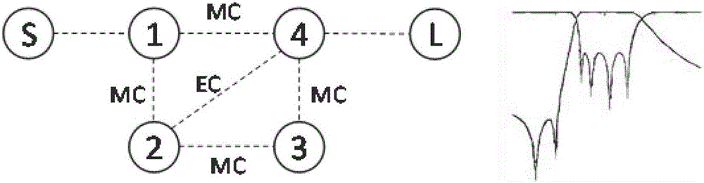
[0030] Such as figure 1 As shown, two transmission zeros are generated on the left side of the passband, and four consecutive cavities generate two cross-couplings, one of which is magnetic coupling, the other is electrical coupling, and the rest are magnetic couplings.

[0031] Among them, EC refers to electrical coupling, MC refers to magnetic coupling, S is the input end, and L is the output end.

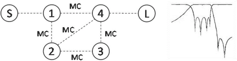
[0032] Such as figure 2 As shown, two transmission zeros are generated on the right side of the passband, and four consecutive cavities generate two cross-couplings, both of which are magnetic couplings, and the rest of the couplings are also magnetic couplings.

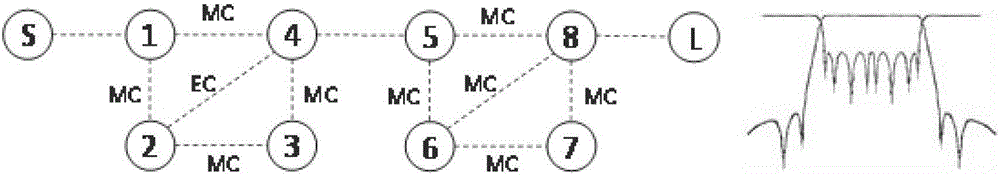
[0033] Such as image 3 As shown, two transmission zeros are generated...


PUM


Abstract

The invention discloses a cavity filter. The cavity filer comprises a metal cavity and a metal cover plate which is positioned on the metal cavity, wherein the metal cavity comprises at least eight resonance cavities which are coupled in sequence; a resonance rod is arranged in each resonance cavity; and the resonance rods in the first and the last resonance cavities are connected with an input signal connector and an output signal connector respectively. The coupling between the adjacent resonance cavities is magnetic coupling; coupling windows and coupling rods are arranged between the corresponding resonance cavities on the left and right sides of a passband; four places of crossed coupling is introduced, so that two transmission zero points can be generated on the left and right sides of the passband respectively, and higher out-of-band rejection can be achieved; the outline dimension of the overall filter cavity is not changed; the order of the filter is not increased, and the size of the filter is not enlarged; meanwhile, the cavity filter is easy to process and debug, and low in cost; and the large-batch production of the cavity filter can be achieved.

Description

technical field [0001] The invention relates to the technical field of communication and microwave, in particular to a cavity filter. Background technique [0002] Bandpass filters have very important applications in the fields of communication and microwave technology. The band-pass filter has frequency-selective characteristics and can filter out harmonic signals generated by non-linear devices and interference signals generated by signal intermodulation. The main parameters to measure the performance index of the band-pass filter are pass-band frequency and relative bandwidth, out-of-band suppression range, pass-band insertion loss, pass-band standing wave, etc. [0003] At present, there are a variety of implementation forms of bandpass filters, such as LC bandpass filters composed of capacitors and inductors, microstrip bandpass filters, dielectric bandpass filters, Fbar bandpass filters, MEMS bandpass filters , LTCC bandpass filter and cavity filter, etc. Among them...

Claims


Application Information

Patent Timeline
Patent Type & Authority Applications(China)
IPC IPC(8): H01P1/208
CPCH01P1/208
Inventor 邓庆文范童修卢胜军
Owner 36TH RES INST OF CETC
Why Eureka
Try Eureka