

Method and structure for improving rigidity of subway vehicle antenna support
A vehicle antenna and antenna bracket technology, which is applied in the field of rail vehicles, can solve the problems of steel structure design ideas that cannot meet the requirements, cannot design large bending stiffness, and reduce the main frequency of the structural mode, so as to achieve low density, easy replacement and installation, and optimization Effects on Structural Properties
- Summary
- Abstract
- Description
- Claims
- Application Information
AI Technical Summary
Problems solved by technology
Method used
Image

Examples
Embodiment 1
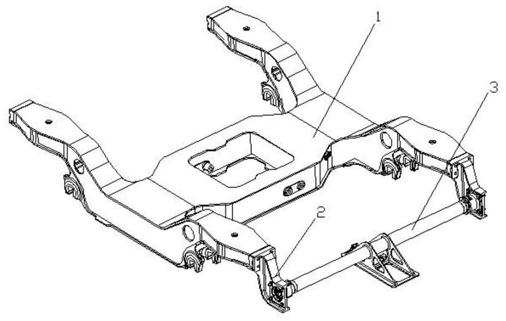
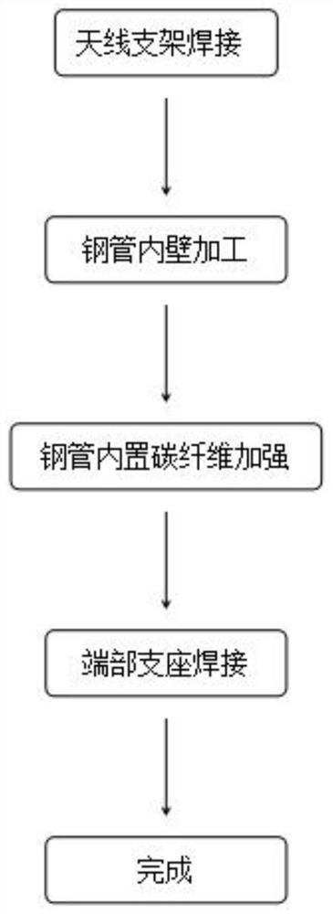
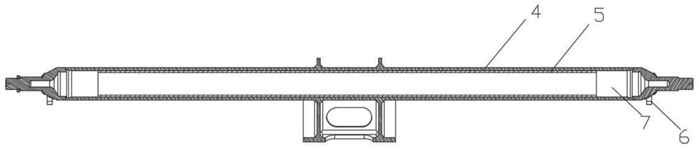
[0032] Such as figure 1 and figure 2 As shown, in view of the problems existing in the actual operation of the above-mentioned subway, a method for improving the stiffness of the antenna bracket 3 of the subway vehicle is proposed. The carbon fiber reinforcing tube 5 is installed inside, without changing the external dimensions of the antenna support 3 and without greatly increasing the quality of the structure of the antenna support 3, the bending stiffness of the antenna support 3 is improved, thereby increasing the main frequency of bending vibration of the antenna support 3 , the concrete steps of the method of the present embodiment are as follows:
[0033] Step 1, welding the steel pipe 4 of the antenna support 3: welding the steel pipe 4 to form the frame of the antenna support 3, and reserving the installation positions of the end supports 6 at both ends of the antenna support 3;
[0034] Step 2, increase the friction force of the inner wall of the steel pipe 4: the...
Embodiment 2
[0039] Such as image 3 As shown, in step 3 in Example 1, the carbon fiber reinforced pipe 5 is continuously and uninterruptedly arranged in the steel pipe 4, and carbon fiber reinforced pipes 5 of different thicknesses are placed in the steel pipe 4, and the length of the carbon fiber reinforced pipe 5 is 1540mm, do bending mode experiment, get as follows Figure 4 The bending mode shape diagram of the bending mode, the analysis of the bending mode experiment results as follows Figure 5The relationship between the wall thickness of the carbon fiber reinforced tube 5 and the bending mode frequency;
[0040] When the wall thickness of the carbon fiber reinforced pipe 5 is 3 mm, the bending frequency of the steel pipe 4 is 70 Hz;
[0041] When the wall thickness of the carbon fiber reinforced pipe 5 is 4 mm, the bending frequency of the steel pipe 4 is 84 Hz;
[0042] When the wall thickness of the carbon fiber reinforced pipe 5 is 5 mm, the bending frequency of the steel pi...
Embodiment 3
[0046] Such as Figure 6 As shown, the difference from Example 2 is that in Step 3 of Example 1, the carbon fiber reinforced pipes 5 are distributed symmetrically in multiple sections in the steel pipe 4, and from the middle to both ends of the steel pipe 4, the carbon fiber reinforced pipes The length of 5 becomes shorter successively, and the positions between the carbon fiber reinforced pipes 5 are fixed by positioning blocks 7 .
[0047] exist Figure 4 In the bending mode shape diagram of the steel pipe 4, the middle part of the steel pipe 4 is the area with the largest stiffness change, which is also the area where cracks appear. However, from the middle to both ends of the steel pipe 4, the rigidity requirements of the structure are getting lower and lower, so the middle part of the steel pipe 4 is the structure The key strengthening position of the steel pipe 4 is the non-key strengthening position.
[0048] Preferably, the length of the carbon fiber reinforced pipe ...
PUM
| Property | Measurement | Unit |
|---|---|---|
| Thickness | aaaaa | aaaaa |
| Length | aaaaa | aaaaa |
| Thickness | aaaaa | aaaaa |
Abstract
Description
Claims
Application Information