Automatic gear shaft assembling machine

A gear shaft and assembly machine technology, which is applied to assembly machines, metal processing equipment, manufacturing tools, etc., can solve the problems of inaccurate gear shaft assembly, inaccurate shaft clamping position, and high defective product rate, and achieve continuous automatic assembly , easy operation and simple structure

Inactive Publication Date: 2018-01-12
DONGGUAN RONGGONG AUTOMATION TECH CO LTD
View PDF9 Cites 23 Cited by
  • Summary
  • Abstract
  • Description
  • Claims
  • Application Information

AI Technical Summary

Problems solved by technology

[0003] Most of the existing gear shaft assembly is to use two parallel conveying plates with intervals between the ball bearing and the connecting piece of the shaft for conveying. For the bearing feeding device, each processing device is positioned by the clampi

Method used


Image

  • Automatic gear shaft assembling machine
  • Automatic gear shaft assembling machine
  • Automatic gear shaft assembling machine

Examples


Embodiment Construction

[0037] In order to enable those skilled in the art to better understand the technical solution of the present invention, the present invention will be described in detail below in conjunction with the accompanying drawings. The description in this part is only exemplary and explanatory, and should not have any limiting effect on the protection scope of the present invention. .

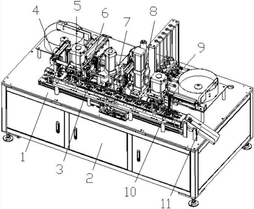
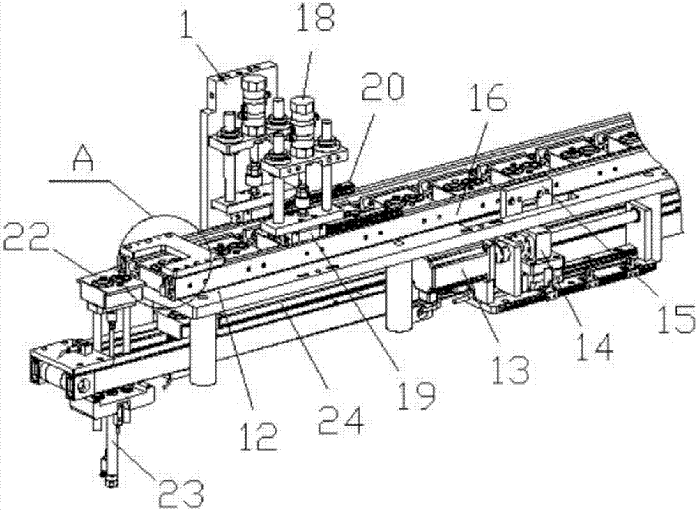
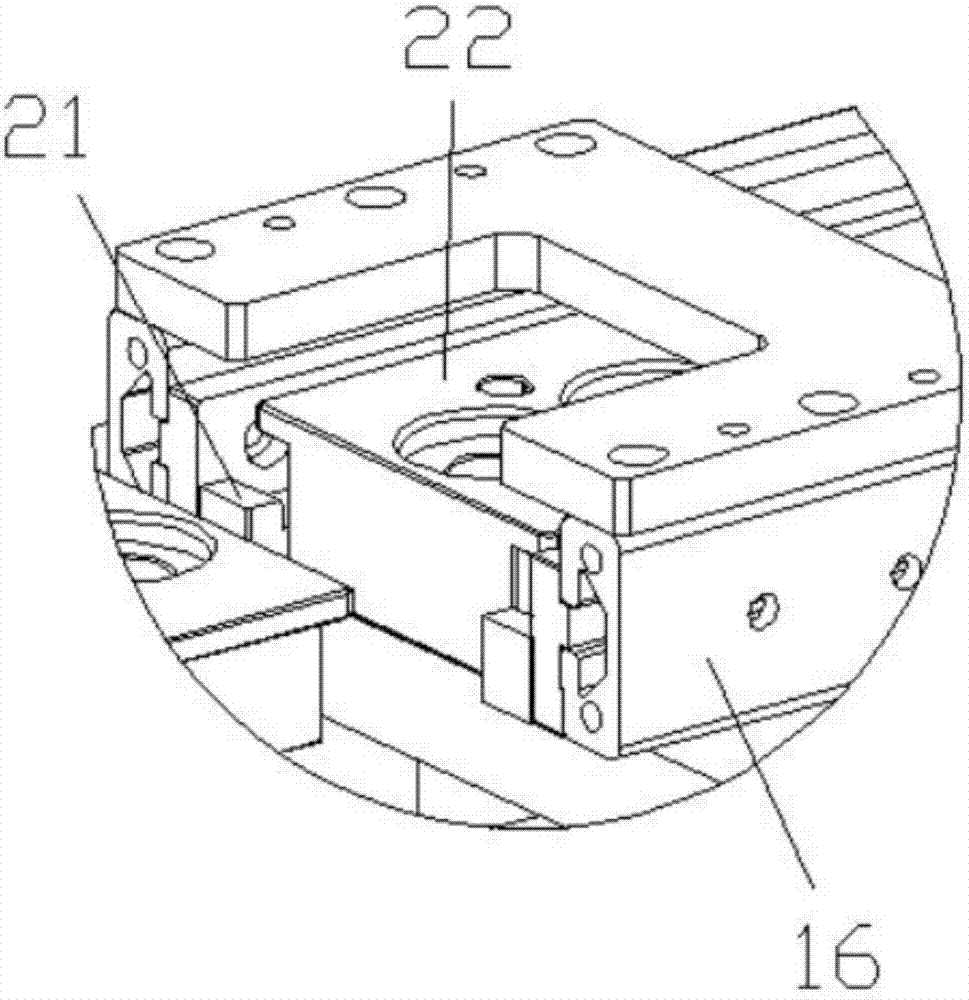
[0038] Such as Figure 1-Figure 12 As shown, the specific structure of the present invention is: a gear shaft automatic assembly machine, which includes a frame 1 and a power distribution control box 2, the frame 1 is provided with a carrier conveying device 3, and the carrier The conveying device 3 includes a carrier conveying seat 12, the front and rear sides of the carrier conveying seat 3 are provided with a carrier feeding movable cylinder 13, and the carrier feeding movable cylinder 13 is connected with a carrier feeding movable seat 14 , the carrier feed movable block 16 is connected with a lef...


PUM


Abstract

The invention relates to an automatic gear shaft assembling machine. The rack is provided with a carrier conveying device. The carrier conveying device comprises a carrier conveying base. Carrier feeding movable air cylinders are arranged on the front side and the rear side of the carrier conveying base and connected with a carrier feeding movable base. The carrier feeding movable base is connected with a carrier feeding movable block. A carrier feeding clamping block matched with a carrier is arranged on the inner side of the carrier feeding movable block. A carrier feeding lifting matched sliding rail is arranged at the upper portion of the carrier feeding movable block and matched with a carrier feeding lifting matched sliding block. The upper portion of the carrier feeding lifting matched sliding block is matched with a carrier feeding lifting air cylinder on the rack. The rack is provided with a ball bearing feeding device, a shaft rod feeding device, an overturning device, a clamping ring feeding device, a gear feeding device, a clamping bearing feeding device and a discharging mechanical arm. According to the automatic gear shaft assembling machine, automatic ball bearing and shaft rod assembling can be achieved, and the assembling efficiency and the yield are greatly improved.

Description

technical field [0001] The invention relates to the field of processing equipment for gear shafts, in particular to an automatic assembly machine for gear shafts. Background technique [0002] The gear shaft is a commonly used component, mainly including ball bearings, shafts, gears, and snap rings and snap bearings for gear positioning. The ball bearings and shafts are sleeved together, and the shaft is sleeved with The gear, the lower part of the gear is locked by the snap ring, and the upper part is positioned by the clamping bearing. The assembly needs to use the assembly machine. [0003] Most of the existing gear shaft assembly is to use two parallel conveying plates with intervals between the ball bearing and the connecting piece of the shaft for conveying. For the bearing feeding device, each processing device is positioned by the clamping device that cooperates with the shaft at the lower part. It is easy for the clamping device to be inaccurate or even miss the cl...

Claims


Application Information

Patent Timeline
IPC IPC(8): B23P21/00
Inventor 邓君杨坤
Owner DONGGUAN RONGGONG AUTOMATION TECH CO LTD
Why Eureka
Try Eureka