Vacuum cavity of multi-cavity structure

A vacuum cavity and cavity structure technology, which is applied in the direction of transportation, packaging, conveyors, etc., to achieve the effect of reasonable structure design, high strength and good stability

Pending Publication Date: 2018-01-12
HANGZHOU ECHO SCI TECH
View PDF6 Cites 0 Cited by
  • Summary
  • Abstract
  • Description
  • Claims
  • Application Information

AI Technical Summary

Problems solved by technology

[0007] The technical solution adopted by the present invention to solve the above problems is: the multi-cavity structure vacuum cavity includes a rear baffle, a front baffle, a right baffle, a left baffle and a bottom plate, and the rear baffle, front baffle, right The baffle, the left baffle and the bottom plate are connected to each other, and it is characterized in that it also includes upper structural beams, transverse structural beams, lower structural beams, transverse partitions, straight partitions, upper slide rails, lower slide rails, support rods, and cut raw bricks , transmission chain disc and transmission chain, described transverse structural beam, upper structural beam and lower structural beam are fixed, transverse diaphragm is connected with straight diaphragm, transverse structural beam is connected with right baffle plate and left baffle plate, this transverse structural beam, The upper structural beam, the lower structur

Method used


Image

  • Vacuum cavity of multi-cavity structure
  • Vacuum cavity of multi-cavity structure
  • Vacuum cavity of multi-cavity structure

Examples


Embodiment Construction

[0020] The present invention will be further described in detail below in conjunction with the accompanying drawings and examples. The following examples are explanations of the present invention and the present invention is not limited to the following examples.

[0021] Example.

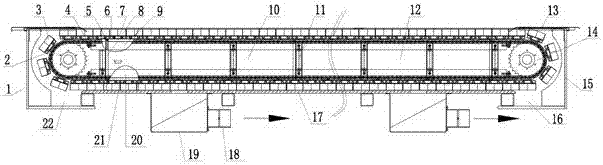
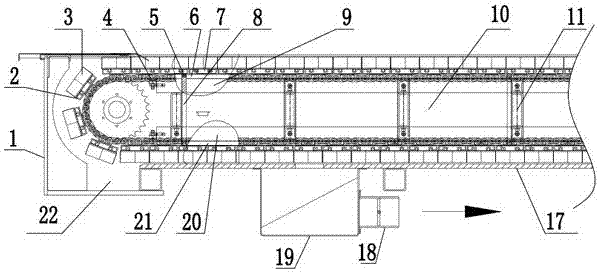
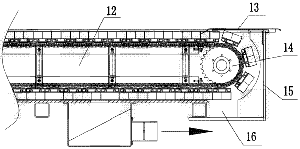
[0022] see Figure 1 to Figure 4 The multi-cavity structure vacuum cavity of this embodiment includes a rear baffle 1, a front baffle 15, a right baffle 27, a left baffle 28, a bottom plate 17, an upper structural beam 9, a transverse structural beam 11, a lower structural beam 20, a horizontal Dividing plate 8, straight dividing plate 26, upper slide rail 6, lower slide rail 21, support bar 2, cut raw brick 3, transmission chain disc 14 and transmission chain 23.

[0023] The rear baffle 1, the front baffle 15, the right baffle 27, the left baffle 28 and the bottom plate 17 of the present embodiment are connected to each other to form a sealed vacuum chamber structure; the upper part area is cove...


PUM


Abstract

The invention relates to a vacuum cavity of a multi-cavity structure, and belongs to the technical field of cutting. The vacuum cavity comprises a rear baffle, a front baffle, a right baffle, a left baffle, a bottom plate, an upper structure beam, a transverse structure beam, a lower structure beam, a transverse division plate, a straight division plate, an upper sliding rail, a lower sliding rail, a supporting rod, a cutting bristle block, a transmission chain disc and a transferring chain; the rear baffle, the front baffle, the right baffle, the left baffle and the bottom plate form a sealedvacuum cavity structure; the transverse structure beam, the upper structure beam and the lower structure beam are fixed; the transverse division plate is connected with the straight division plate; the transverse structure beam is connected with the right baffle and the left baffle; the upper structure beam is provided with the upper sliding rail, and the lower structure beam is provided with thelower sliding rail; the cutting bristle block is arranged on the supporting rod; the bottom of the supporting rod movably makes contact with the upper sliding rail and the lower sliding rail; the transmission chain disc is in transmission connection with the transferring chain; and the transferring chain drives the supporting rod and the cutting bristle block to move. The vacuum cavity of the multi-cavity structure is reasonable in structure, high in strength and good in stability and is provided with a plurality of inner cavity structures, so that the vacuum adsorbing function of a working area is achieved.

Description

technical field [0001] The invention relates to a vacuum cavity, in particular to a vacuum cavity with a multi-cavity structure, which belongs to the technical field of cutting materials. Background technique [0002] The existing vacuum chamber structure, the main body is two flat side plates, a front end plate, a rear end plate and a flat bottom plate welded to each other. strength between. [0003] During the use of the above-mentioned vacuum chamber, when the negative pressure is large, the side plate is prone to local elastic deformation, which affects the loosening of the transmission chain. It is easy to be pulled off; and it is difficult to ensure the accuracy of cutting, and it is difficult to assemble. [0004] The publication date is March 02, 2006, and the publication number is 205060659U in the Chinese patent, which discloses a utility model patent named "Cutting Machine Vacuum Adsorption Mechanism". This patent includes a vacuum adsorption mechanism body loc...

Claims


Application Information

Patent Timeline
IPC IPC(8): B65G17/46
Inventor 方云科张东升
Owner HANGZHOU ECHO SCI TECH
Why Eureka
Try Eureka