
High-efficiency petroleum pipeline lifting device

A technology of oil pipelines and lifting devices, which is applied in the direction of transportation and packaging, load hanging components, etc., can solve the problems of pipeline outer wall damage, difficult balance of pipelines, poor fixation, etc., and achieve the effect of improving efficiency, large friction, and maintaining balance

Inactive Publication Date: 2018-01-12
CHENGDU KESHENG PETROLEUM TECH
View PDF5 Cites 4 Cited by
  • Summary
  • Abstract
  • Description
  • Claims
  • Application Information

AI Technical Summary

Problems solved by technology

[0003] The technical problem to be solved by the present invention is that the existing pipeline sling can only lift one pipeline at a time, and the pipeline is poor in fixity during the lifting and moving process, and will swing with the swaying of the sling, making it difficult to keep the pipeline in balance , and may slip out of the sling, which will easily cause damage to the outer wall of the pipeline during the installation process. The purpose is to provide a high-efficiency oil pipeline lifting device, which can lift two pipelines at the same time, greatly improving the efficiency of transportation and installation. At the same time, the partition block set between the two pipes can not only maintain the balance on both sides of the pipes and prevent them from swinging left and right, but also play a good role in protecting the adjacent sides of the two pipes and buffering the lifting process. shaking force

Method used


Image

  • High-efficiency petroleum pipeline lifting device

Examples


Embodiment

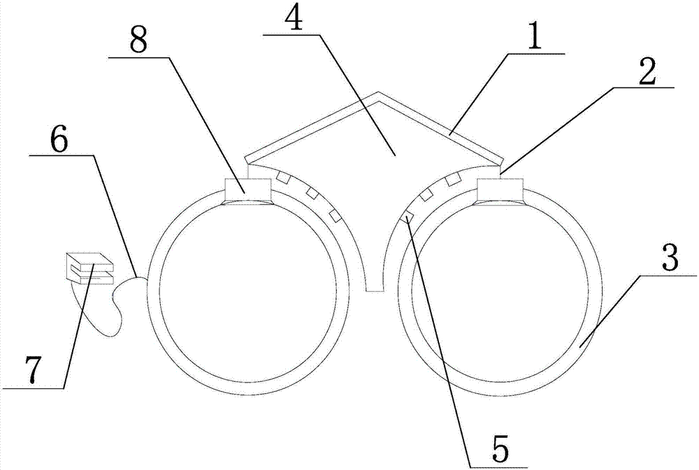
[0021] Such as figure 1 As shown, the high-efficiency oil pipeline lifting device of the present invention includes two hanging plates 1 connected in sequence, the angle between the two hanging plates 1 is 120-150° and the opening of the included angle faces downward, and each hanging plate The two ends of the lower side of 1 are respectively connected with suspension rings 3 through suspension ropes 2. The size of the suspension rings 3 matches the outer diameter of the oil pipeline, and the suspension rings 3 are made of rubber materials. The two suspension plates 1 There is a partition block 4 between them. The two sides of the partition block 4 are arc-shaped and match the arc shape of the outer wall of the oil pipeline. The arc-shaped sides of the partition block 4 are vertically connected with multiple supports along the arc length direction. Block 5, the end face of support block 5 is provided with damping spring.

[0022] The oil pipeline spreader of the present inven...


PUM


Abstract

The invention discloses a high-efficiency petroleum pipeline lifting device. The high-efficiency petroleum pipeline lifting device comprises two lifting plates which are sequentially connected, lifting rings are connected to the two ends of one side of the lower portion of each lifting plate through lifting ropes, the size of the lifting rings is matched with the outer diameter size of petroleum pipelines, and the lifting rings are made of rubber materials; a partitioning block is arranged between the two lifting plates, the two side faces of the partitioning block are each shaped like a circular arc, the circular-arc-shaped side faces are matched with the arc-shaped outer wall faces of the petroleum pipelines, multiple supporting blocks are connected to the side faces of the partitioningblock, and a damping spring is arranged on the end face of each supporting block. According to the petroleum pipeline lifting device, two pipelines can be simultaneously lifted, and the transportationand installation efficiency is greatly improved; meanwhile, the partitioning block arranged between the two pipelines not only can keep the balance of the two sides of the pipelines to avoid the condition that the pipelines shake left and right, but also can achieve a good protecting effect on the adjacent sides of the two pipelines and achieve the effect of buffering the sloshing force generatedin the lifting process.

Description

technical field [0001] The invention relates to an oil pipeline transportation, in particular to a high-efficiency oil pipeline lifting device. Background technique [0002] Petroleum, one of the main objects of geological exploration, is a viscous, dark brown liquid known as the "blood of industry". There are oil reserves in parts of the upper crust. The main component is a mixture of various alkanes, naphthenes and aromatic hydrocarbons. The oil-forming mechanism of petroleum has two theories of biosedimentary oil and petrochemical oil. The former is more widely accepted. It is believed that oil is formed by organisms in ancient oceans or lakes after a long evolution. It belongs to biosedimentary oil and is non-renewable. It is believed that petroleum is generated from the carbon in the earth's crust itself, has nothing to do with biology, and is renewable. Petroleum is mainly used as fuel oil and gasoline, and is also a raw material for many chemical industry products,...

Claims


Application Information

Patent Timeline
Patent Type & Authority Applications(China)
IPC IPC(8): B66C1/02B66C1/22
Inventor 贺昶明
Owner CHENGDU KESHENG PETROLEUM TECH
Learn More