Dolly chain driven bridge cantilever crane with balancing counterweight

A technology of counterweights and cranes, which is applied in the direction of walking bridge cranes, cranes, mechanical equipment, etc., and can solve the problems of dispatching operations with the help of other transportation equipment, using low-level work, and small tonnage

Inactive Publication Date: 2018-01-12
林霞
View PDF0 Cites 2 Cited by
  • Summary
  • Abstract
  • Description
  • Claims
  • Application Information

AI Technical Summary

Problems solved by technology

[0002] Existing bridge cranes are used in enterprise workshops. The products and raw materials in the workshop need to be transported to the next workshop or other departments in real time; The beam runs back and forth, and the crane can only run back and forth along the cart rails on the cross columns on both sides of the workshop. In this way, the range of goods that the crane hook can lift is within the plane surrounded by the two ends of the two cart rails in the workshop. When the goods on the edge of this plane need to be hoisted, the hook will be pulled obliquely, and the items farther away from this plane (such as outside the workshop door, outside the span) cannot be hoisted. At this time, they can only be transferred by other transportation equipment. , Usually the car drives into the workshop to lift the goods under the hook. If some cars cannot drive in, a track is laid horizontally between the workshop and the next-door workshop, and the special rail car is driven to the hook to deliver the goods, and some are in the workshop. A special cantilever crane is set up a

Method used


Image

  • Dolly chain driven bridge cantilever crane with balancing counterweight
  • Dolly chain driven bridge cantilever crane with balancing counterweight
  • Dolly chain driven bridge cantilever crane with balancing counterweight

Examples


Embodiment approach

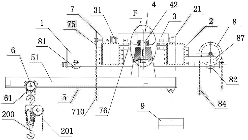
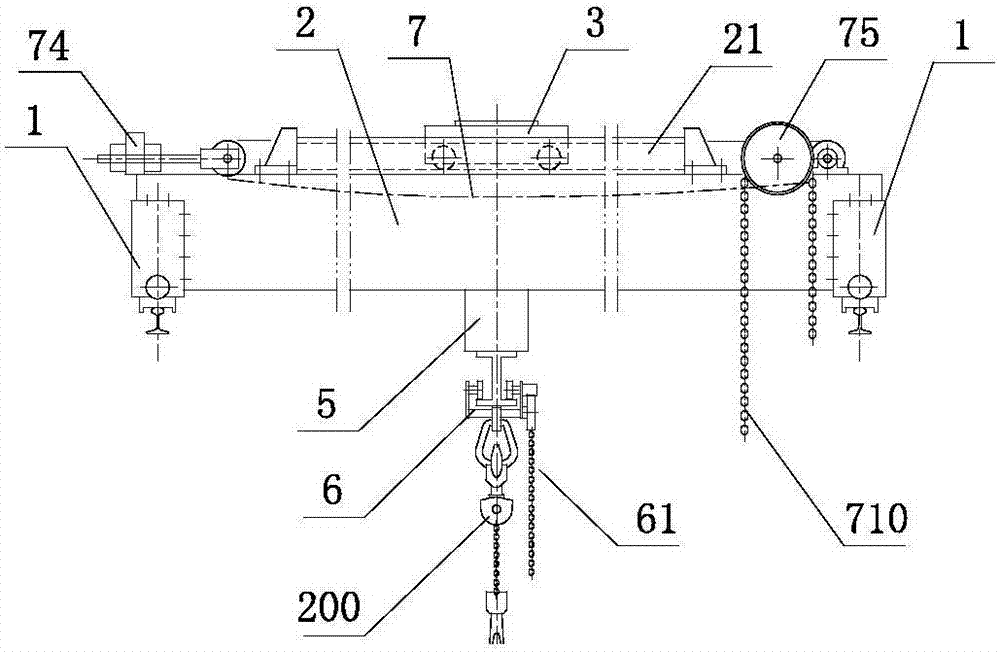
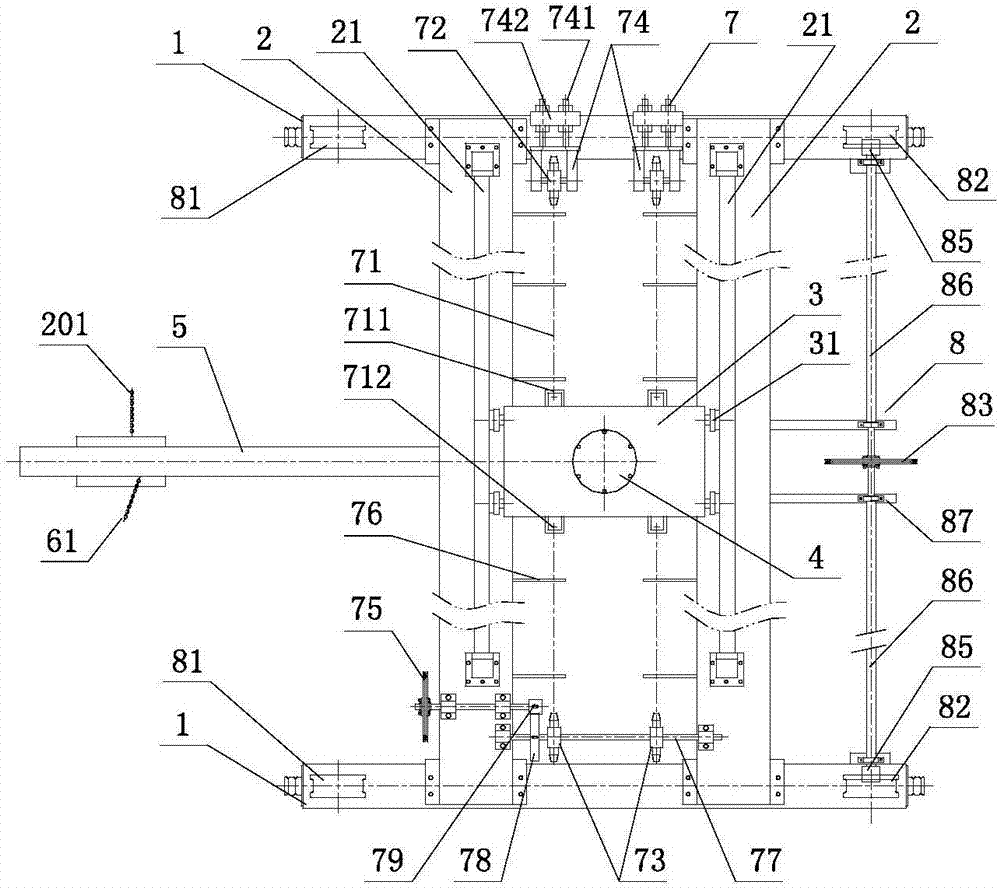
[0029] Such as figure 1 , figure 2 , image 3As shown, a bridge type cantilever crane driven by a trolley chain and with a counterweight includes two end girders 1 and two main girders 2, which form a double-girder bridge structure; between the two end girders, there is Hand cart running device 8; above the two main girders 2 are provided with an inverted "U" shaped track 21, and the opening of the track is towards the inner side of the main girder; a running trolley 3 is connected between the two rails 21; The wheels 31 on the running trolley run on the track; the running trolley is provided with a chain drive device 7; the center of the running trolley is provided with a rotating mechanism 4; the rotating mechanism is internally connected with a thrust bearing; The lower end of the boom shaft in the rotating mechanism is connected with the cantilever member 5; one end of the cantilever beam 51 on the cantilever member is connected with the hand-pulled sports car 6 with a ...


PUM


Abstract

The invention discloses a dolly chain driven bridge cantilever crane with a balancing counterweight. The bridge cantilever crane comprises two end beams and two main beams which form a two-beam cranespan structure, wherein a hand-pulled trolley running device is arranged between the two end beams; inverted U-shaped tracks are arranged on the two main beams; a running dolly is arranged between andconnected with the two tracks; the running dolly is provided with a chain drive unit; the central part of the running dolly is provided with a rotating mechanism; a thrust bearing is connected with the interior of the rotating mechanism; the lower end of a suspender shaft in the rotating mechanism is connected with a cantilever member; one end of a cantilever beam on the cantilever member is connected with a hand-pulled trolley, and the balancing counterweight is hung on the other side of the cantilever beam; the hand-pulled trolley can horizontally move to and fro along the cantilever beam;a hand-pulled chain hoist is hung below the hand-pulled running trolley and capable of hoisting cargos; and the cantilever beam is located below the two main beams and capable of carrying out rotation, and can stretch out of a workshop for operation.

Description

technical field [0001] The present application relates to the field of cranes, in particular to a trolley chain-driven bridge-type cantilever crane with a counterweight. Background technique [0002] Existing bridge cranes are used in enterprise workshops. The products and raw materials in the workshop need to be transported to the next workshop or other departments in real time; The beam runs back and forth, and the crane can only run back and forth along the cart rails on the cross columns on both sides of the workshop. In this way, the range of goods that the crane hook can lift is within the plane surrounded by the two ends of the two cart rails in the workshop. When the goods on the edge of this plane need to be hoisted, the hook will be pulled obliquely, and the items farther away from this plane (such as outside the workshop door, outside the span) cannot be hoisted. At this time, they can only be transferred by other transportation equipment. , Usually the car drive...

Claims


Application Information

Patent Timeline
IPC IPC(8): B66C17/04B66C11/16B66C11/10B66C11/06B66C9/02B66C9/14F16B39/04F16B37/00
Inventor 黄滨林霞
Owner 林霞
Why Eureka
Try Eureka