Speed changer and automatic gear-shifting executor

An automatic gear shifting and actuator technology, applied in clutches, transmission control, mechanical drive clutches, etc., can solve the problems of low mechanical transmission efficiency, prolonged dynamic response time, etc., to shorten dynamic response time, eliminate axial clearance, The effect of precise axial movement displacement

Inactive Publication Date: 2018-01-12
SCHAEFFLER TECH AG & CO KG
View PDF8 Cites 3 Cited by
  • Summary
  • Abstract
  • Description
  • Claims
  • Application Information

AI Technical Summary

Problems solved by technology

[0005] The problem solved by the present invention is that the mechanical transmission effi...

Method used


Image

  • Speed changer and automatic gear-shifting executor

Examples


Embodiment Construction

[0020] In order to make the above objects, features and advantages of the present invention more comprehensible, specific embodiments of the present invention will be described in detail below in conjunction with the accompanying drawings.

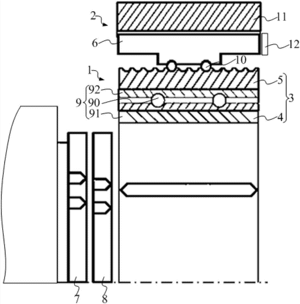
[0021] The transmission includes an automatic shift actuator. refer to figure 1 , the automatic shift actuator includes: a synchronizer 1 and a drive unit 2, and the synchronizer 1 includes an adapter sleeve 3. The adapter sleeve 3 includes: a coaxial body ring 4 and a drive ring 5 , the drive ring 5 is sleeved outside the body ring 4 , and the drive ring 5 and the body ring 4 are connected in a relatively rotatable and synchronous axial movement connection. The drive unit 2 has an output part 6 set outside the drive ring 5, and the drive unit 2 is used to output the rotary motion around the central axis of the drive ring 5 through the output part 6; between the drive ring 5 and the output part 6 is a screw drive , the screw drive is use...


PUM


Abstract

The invention relates to a speed changer and an automatic gear-shifting executor. The automatic gear-shifting executor comprises a synchronizer and a driving unit. The synchronizer comprises a joiningsleeve including a body ring and a driving ring. The body ring and the driving ring are coaxially arranged. The driving ring sleeves outside the body ring. The driving ring is connected with the bodyring in a relatively rotating manner and a synchronous axial-moving manner. The driving unit is provided with an output part sleeving outside the driving ring and used for outputting rotary motion rotating around a central axis of the driving ring through the output part. Lead-screw driving is achieved between the driving ring and the output part. The lead-screw driving is used or converting rotary motion of the output part into axial motion of the driving ring and the body ring. The automatic gear-shifting executor in the technical scheme has high mechanical driving efficiency and short dynamic response time.

Description

technical field [0001] The invention relates to the technical field of transmissions, in particular to a transmission and an automatic shift actuator. Background technique [0002] An existing automatic shift actuator includes: a synchronizer, a shift fork and a drive unit. The synchronizer includes: an engaging sleeve, an engaging ring gear arranged on the gear to be engaged, and a synchronizing ring axially distributed with the engaging ring gear. The shift fork is sheathed outside the adapter sleeve, and the drive unit is used to axially drive the shift fork so that the shift fork moves the adapter sleeve axially. In the disengaged state, the synchronizer ring is located outside the mating sleeve and is axially separated from the mating ring gear. [0003] The car ECU (Electronic Control Unit, referred to as ECU) determines when it is necessary to shift gears based on signals such as the accelerator opening and vehicle speed, and controls the drive unit to act. The dri...

Claims


Application Information

Patent Timeline
IPC IPC(8): F16H61/26F16D23/04
Inventor 张煜
Owner SCHAEFFLER TECH AG & CO KG
Why Eureka
Try Eureka