A display system and method

A display system and a technology for displaying light, which are applied in the fields of display and projection, can solve problems such as error-prone, poor color uniformity, and large differences in spot dispersion, and achieve reduced distortion and color deviation, and small differences in spot dispersion. Improve the effect of display effect

Active Publication Date: 2019-09-20
APPOTRONICS CORP LTD
View PDF18 Cites 0 Cited by
  • Summary
  • Abstract
  • Description
  • Claims
  • Application Information

AI Technical Summary

Problems solved by technology

[0002] Existing displays mainly include a light source, a first photoelectric modulator, an imaging system, a second photoelectric modulator, and a projection screen. According to a certain image signal, two photoelectric modulators need to be used to control the light beam, and the structure is complex. error-prone
For the design of some displays, the internal reflection prism is used to change the direction of light propagation. Because the light cone angle expanded by the internal reflection prism is too large, the spherical aberration and astigmatism formed will cause the light spot on the photoelectric modulator to have a large difference in dispersion. Large, resulting in distortion and color deviation in the system imaging, poor color uniformity, and the quality of imaging display is not ideal

Method used


Image

  • A display system and method
  • A display system and method
  • A display system and method

Examples


Embodiment 1

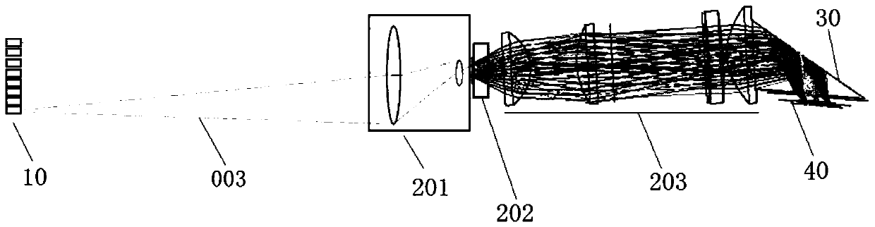
[0018] Such as figure 1 As shown, the display system of this embodiment includes a light source device 10, an optical processing component, a reflection device 30, a spatial light modulator 40, a controller, and a screen; the controller is respectively connected to the light source device 10 and the spatial light modulator 40; The processing component includes a first relay lens group 201 , a dodging rod unit 202 , and a second relay lens group 203 .

[0019] The light source device 10 is a solid-state light source array for emitting multiple light beams; the spatial light modulator 40 includes a plurality of controllable units, that is, pixel units, and a beam of light emitted by each solid-state light source of the light source device 10 corresponds to the spatial light modulator 40 A group of pixel units. It should be noted that the solid-state light sources include lasers and LEDs, and unless otherwise specified, lasers and laser arrays will be used as examples for illust...


PUM


Abstract

The application discloses a display system and method, including a light source device, an optical processing component, a reflection device, and a light modulator. The light source device is used to emit multiple beams of light; the optical processing component is used to adjust the optical path of each beam of light from the light source device so that it is irradiated to the reflection device at a preset light cone angle; the reflection device is used to convert the light from the optical processing component The light beam is reflected to the light modulator; the light modulator is used to modulate the light beam through each controllable unit so as to emit display light that meets requirements. The deviation between the first direction or the second direction of the display system and the horizontal direction has a preset inclination angle. The laser beam emitted by the light source device of the present invention is further modulated in the light modulator, so as to emit display light that is more similar to the desired image, avoiding errors that are prone to occur, and the difference in the dispersion degree of the light spot on the spatial light modulator is smaller, The distortion and color deviation in the imaging of the display system are reduced, and the imaging quality and the display effect of the picture are improved.

Description

technical field [0001] The present application relates to the fields of projection and display, and in particular to a display system and method. Background technique [0002] Existing displays mainly include a light source, a first photoelectric modulator, an imaging system, a second photoelectric modulator, and a projection screen. According to a certain image signal, two photoelectric modulators need to be used to control the light beam, and the structure is complex. and prone to errors. For the design of some displays, the internal reflection prism is used to change the direction of light propagation. Because the light cone angle expanded by the internal reflection prism is too large, the spherical aberration and astigmatism formed will cause the light spot on the photoelectric modulator to have a large difference in dispersion. Large, resulting in distortion and color deviation in the system imaging, poor color uniformity, and the quality of imaging display is not idea...

Claims


Application Information

Patent Timeline
Patent Type & Authority Patents(China)
IPC IPC(8): G03B21/20
CPCG03B21/2013G03B21/2033G03B21/2066G03B21/208G03B21/008G03B21/2053G03B21/20G03B21/005G03B21/147
Inventor 胡飞郭祖强李屹
Owner APPOTRONICS CORP LTD
Why Eureka
Try Eureka