Water injection device of an internal combustion engine

A water injection, internal combustion engine technology, applied in mechanical equipment, internal combustion piston engines, combustion engines, etc., can solve the problem of not being able to re-pump and so on

Active Publication Date: 2018-01-12
ROBERT BOSCH GMBH
View PDF6 Cites 3 Cited by
  • Summary
  • Abstract
  • Description
  • Claims
  • Application Information

AI Technical Summary

Problems solved by technology

However, the problem arises in some pump types that the pump type is not able to re-pump water from the lower water line again

Method used


Image

  • Water injection device of an internal combustion engine

Examples


Embodiment Construction

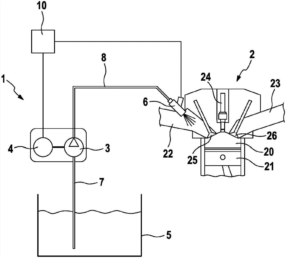
[0016] Refer to the following figure 1 The device 1 for injecting water of the internal combustion engine 2 is explained in detail.

[0017] exist figure 1 The internal combustion engine 2 is schematically shown in . The internal combustion engine 2 comprises a combustion chamber 20 in which a piston 21 can reciprocate. Reference numeral 22 denotes a suction pipe through which air is supplied to the combustion chamber. Exhaust air is conducted through an exhaust pipe 23 . Here, an intake valve 25 is arranged on the suction pipe and an outlet valve 26 is arranged on the exhaust pipe 23 . In addition, reference numeral 24 denotes a fuel injection valve.

[0018] According to the invention, the device 1 for spraying water comprises a pump 3 and an electric drive 4 for driving the pump 3 . Furthermore, a water tank 5 is provided, which is connected to the pump 3 via a first line 7 .

[0019] as from figure 1 It can be seen that the pump 3 is arranged higher than the water ...


PUM


Abstract

The invention relates to a water injection device of an internal combustion engine, comprising a water tank (5) for storing water, a pump (3) for pumping the water, said pump (3) being arranged higherthan the water tank (5) and being connected to the water tank via a first line (7), a water injection valve (6) for injecting water, said valve being connected to the pump (3) via a second line (8),a drive (4) for driving the pump (3), and a control unit (10) which is designed to open the water injection valve (6) in order to suction water out of the water tank (5) to the pump (3) using a vacuumpresent in front of the water injection valve (6) when the lines and the pump are empty.

Description

technical field [0001] The invention relates to a water injection system for an internal combustion engine and to an internal combustion engine of this type. Background technique [0002] It is known in internal combustion engines to achieve an increase in power and / or a reduction in consumption by means of water injection. Here, there is usually a separate water injection system in order to achieve the water injection. Here, the problem area is that the water system can freeze, especially if the vehicle is parked. Here, there is the risk that components of the water system will be damaged by the frozen water. [0003] A water spray system is known from FR 2339061 in which water is sprayed directly into the suction pipe by means of a spray pump in the absence of a spray valve. Here, in the parked state, water remains in the jet pump and water lines. However, uncontrollable jet pumps as known from this document are not suitable for spraying water accurately in order to in...

Claims


Application Information

Patent Timeline
Patent Type & Authority Applications(China)
IPC IPC(8): F02M25/022F02M25/028F02B47/02
CPCF02B47/02F02M25/0221F02M25/028Y02T10/12
Inventor S·奥贝格费尔M·诺尔普A·艾兴多夫
Owner ROBERT BOSCH GMBH
Why Eureka
Try Eureka