Cooling electronic devices in a data center

A technology for data centers and cooling systems, applied in electrical equipment structural parts, electrical digital data processing, digital data processing parts and other directions, can solve the problems of speed, efficiency and cost at a huge cost

Active Publication Date: 2018-01-12
GOOGLE LLC
View PDF13 Cites 11 Cited by
  • Summary
  • Abstract
  • Description
  • Claims
  • Application Information

AI Technical Summary

Problems solved by technology

While ad hoc redundancy can be built into computer data centers, server racks, and even individual

Method used


Image

  • Cooling electronic devices in a data center
  • Cooling electronic devices in a data center
  • Cooling electronic devices in a data center

Examples


Embodiment Construction

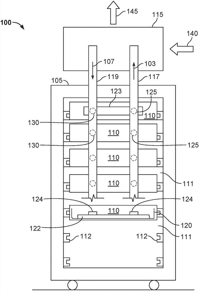
[0048] figure 1 An example system 100 is shown that includes a server rack 105 (eg, a 13-inch or 19-inch server rack) and a plurality of server rack subassemblies 110 mounted within the rack 105 . Although a single server rack 105 is shown, the server rack 105 may be one of a plurality of server racks within the system 100, which may include a server farm or a co-located facility containing various rack-mounted computer systems . Furthermore, while multiple server rack subassemblies 110 are shown mounted within rack 105, there may be only a single server rack subassembly. Typically, the server rack 105 defines a plurality of slots 107 arranged in an orderly and repeating manner within the server rack 105, and each slot 107 is a space in the rack into which a corresponding server rack subassembly 110 can be placed and moved. into this space. For example, the server rack subassembly may be supported on rails 112 that project from opposite sides of the rack 105 and may define ...


PUM


Abstract

A server rack thermosiphon system (100) includes a plurality of evaporators (123), each evaporator including a thermal interface for one or more heat-generating server rack devices (124); at least onecondenser (115) mounted to an external structure of a server rack (105), the condenser including a fluid-cooled heat transfer module; a liquid conduit (119) that fluidly couples each of the evaporators to the condenser to deliver a liquid phase (107) of a working fluid from the condenser to the evaporators; and a vapor conduit (117) that fluidly couples each of the evaporators to the condenser todeliver a mixed phase (103) of the working fluid from the evaporators to the condenser.

Description

technical field [0001] This document relates to systems and methods for utilizing thermosiphons to provide cooling to electronic equipment, such as computer server racks and related equipment in computer data centers. Background technique [0002] Computer users are often concerned with the speed (eg, megahertz and gigahertz) of a computer's microprocessor. Many people forget that this speed usually comes at a cost - higher power consumption. This power dissipation also generates heat. That's because, through the simple laws of physics, all that power has to go somewhere, where it ends up being converted to heat. A pair of microprocessors mounted on a single motherboard can draw hundreds of watts or more. Multiply that number by the thousands (or tens of thousands) to do the calculations for many computers in a large data center and get an easy idea of ​​the amount of heat that can be generated. The impact of critical load power in a data center is often compounded when ...

Claims


Application Information

Patent Timeline
IPC IPC(8): H05K7/20
CPCH05K7/20809H05K7/20818G06F1/20G06F2200/201H05K7/2029H05K7/20336H05K7/20545H05K7/20663H05K7/20672H05K7/20681
Inventor S.法尔希奇扬M.K.延加
Owner GOOGLE LLC
Why Eureka
Try Eureka