Check patentability & draft patents in minutes with Patsnap Eureka AI!

Suture device and working method thereof

A suturing device and suture thread technology, applied in the field of suturing devices, can solve the problems of difficulty in finding, hooking, feeling and experience for a long time, difficult and accurate needle threading, etc., so as to avoid adverse consequences, short suturing time and operation low risk effect

Pending Publication Date: 2018-01-16
常州永华医疗器械有限公司
View PDF0 Cites 5 Cited by
  • Summary
  • Abstract
  • Description
  • Claims
  • Application Information

AI Technical Summary

Problems solved by technology

Because of the particularity of blind sewing, not only is it not easy to thread the needle accurately, but it is also difficult to find and hook the thread hole with a hook at one time, and it is easy to unhook when pulling the thread outward, so it takes a long time, feeling and experience

Method used


Image

  • Suture device and working method thereof
  • Suture device and working method thereof
  • Suture device and working method thereof

Examples


Embodiment 1

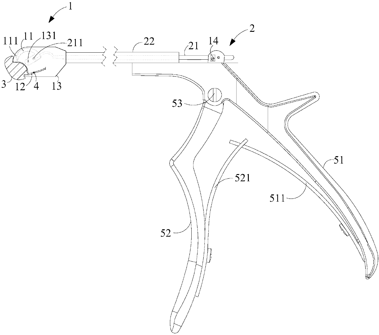
[0030] figure 1 It is a structural diagram of the stapler of the present invention.

[0031] Such as figure 1 As shown, the present embodiment 1 provides a stapler, including: a suturing mechanism 1 and a linkage mechanism 2; wherein the linkage mechanism 2 is adapted to drive the suturing mechanism 1 to suture the tissue 3 to be sutured.

[0032] Among them, the linkage mechanism drives the suture mechanism to move in an arc-shaped trajectory, which is a mechanical movement to ensure the needle distance, depth, and accurate position; due to the advantages of simple operation, flexibility, and small range, it is not only suitable for external sutures, but also especially suitable for narrow paths. Or the use of blind suture operations such as intracavitary patch or suture due to narrow cavity (such as gynecological hip pelvic cavity).

Embodiment 2

[0034] Embodiment 2 also provides a stapler, including: a suturing mechanism, a notch is provided at the front end of the suturing mechanism; the tissue to be sutured is adapted to be inserted into the notch for suturing.

Embodiment 3

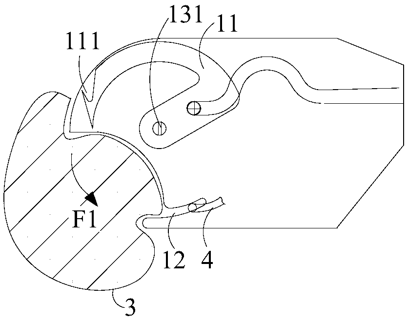
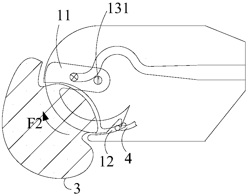
[0036] On the basis of Embodiment 1 and Embodiment 2, the suturing mechanism 1 in this stapler includes: a suture hook 11 with a barb 111 and a thread holding groove 12 . Specifically, when the linkage mechanism 2 drives the suture hook 11 to rotate and pierce the tissue 3 to be sutured, the barb 111 catches the suture 4 from the thread holding groove 12; After passing through the tissue to be sutured 3 and driving the suture thread 4 to pass through the tissue to be sutured 3 again, the suture thread can be ligated by manual means to complete a suturing process. The suturing mechanism is suitable for suturing the tissue to be sutured one by one, that is, only one stitch is sutured for each operation, and then ligated independently, so as to ensure that the tissue to be sutured is not easy to collapse after suturing.

[0037] Preferably, the suture hook 11 is, for example but not limited to, an arc-shaped pointed structure, the barb 111 is located on its outer arc surface, pre...


PUM


Abstract

The invention belongs to the field of medical instruments, and particularly relates to a suture device and a working method thereof. The suture device includes a suture mechanism and a linkage mechanism; the linkage mechanism is suitable for driving a suture hooking needle to move and rotate along an assigned track, and after a tissue to be sutured is pierced by the linkage mechanism, a barb hooksa suture line from a line clamping groove; during rotation of the suture hooking needle, the suture line is driven to penetrate through the tissue to be sutured by the suture hooking needle and thencut off and knotted to achieve suture step by step; the suture device is particularly suitable for being used in blind suture operations (such as suture operations in pelvic cavities in the gynecologydepartment) in which intracavity patching or suture and the like need to be conducted in a narrow path or a narrow cavity; mechanical power is adopted in the suture device to ensure the accuracy of the suture needle pitch, suture depth and suture position, and the suture device has the advantages of being simple to operate, short in suture time, great in effect, low in surgical risk and the like.

Description

technical field [0001] The invention relates to a medical device, in particular to a stapler and a working method thereof. Background technique [0002] Suturing in clinical surgery is an important part of surgery. Due to the advantages of good stability, simple operation, and high suture quality, it has become a trend to use instrumental suture instead of manual suture. [0003] However, suture instruments also have certain limitations in current clinical operations. When suturing internal tissues, especially blind suture operations such as intracavitary patch or suture (such as gynecological pelvic suture), due to the narrow cavity of the tissue to be sutured, the suture operation space is small. , the traditional suture device can no longer meet the suture requirements such as suture stitch distance, suture depth, suture position and so on. And, the suturing method of the wound in the internal stapler used at present is: first suture thread is pierced tissue with needle,...

Claims


Application Information

Patent Timeline
Patent Type & Authority Applications(China)
IPC IPC(8): A61B17/04A61B17/06
Inventor 丁大林史惠忠
Owner 常州永华医疗器械有限公司
Features
  • R&D
  • Intellectual Property
  • Life Sciences
  • Materials
  • Tech Scout
  • Unparalleled Data Quality
  • Higher Quality Content
  • 60% Fewer Hallucinations
Learn More