Integral engine turbine blade mounting and dismounting device and method

A turbine blade, the overall installation technology, applied in the direction of the workpiece clamping device, metal processing, metal processing equipment, etc., can solve the problems of high labor intensity of the operator, easy damage to the turbine disc and blade tenon, time-consuming and other problems, to ensure the installation Improve the quality of disassembly, improve the efficiency of installation and disassembly, and avoid damage

Active Publication Date: 2018-01-16
CHENGDU ENGINE GROUP
View PDF4 Cites 19 Cited by
  • Summary
  • Abstract
  • Description
  • Claims
  • Application Information

AI Technical Summary

Problems solved by technology

Because the impact force is generated by the hammer, if the force is not well controlled, it is easy to damage the turbine disk and the tenon of the blade, so the quality of assembly and disassembly is difficult to be guaranteed; moreover, due to the large number of turbine blades in the whole circle, it is necessary to tap one by one The way of installation and disassembly is very time-consuming, not only the work efficiency is low, but also the labor intensity of the operator is relatively high

Method used


Image

  • Integral engine turbine blade mounting and dismounting device and method
  • Integral engine turbine blade mounting and dismounting device and method
  • Integral engine turbine blade mounting and dismounting device and method

Examples


Embodiment 1

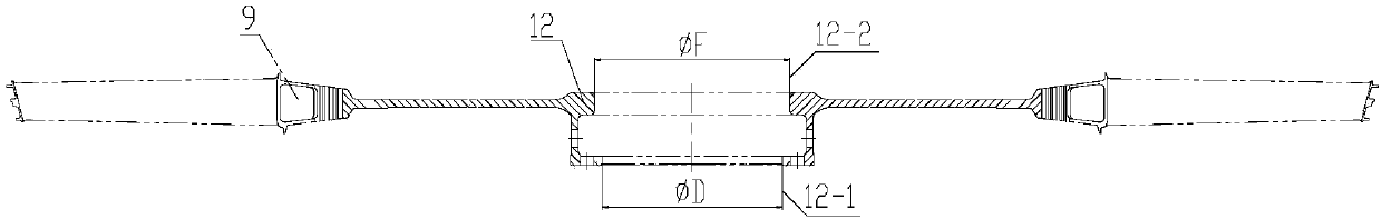
[0046] The engine turbine blade integral installation and removal device in this embodiment is used for installation and removal figure 1 The turbine blades and turbine discs of the engine are shown, and the number of turbine blades in the entire circle is 84.

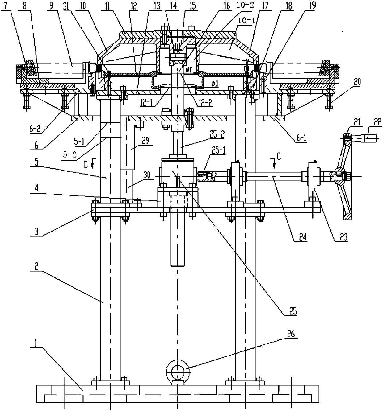
[0047] In this embodiment, the structure of the engine turbine blade overall installation and removal device is as follows: figure 2 As shown, it includes a base 1, a lower column 2, an upper column 5, an elevator 25, an elevator driving assembly, an elevator mounting plate 3, an elevator frame 6, an elevator frame guide rod 30, an elevator frame guide sleeve 29, a pull rod 16, a pull plate 11, Adapter 15 , positioning plate 13 , turbine disc support ring 18 , blade support ring 19 , assembly gland 10 and disassembly gland 27 .

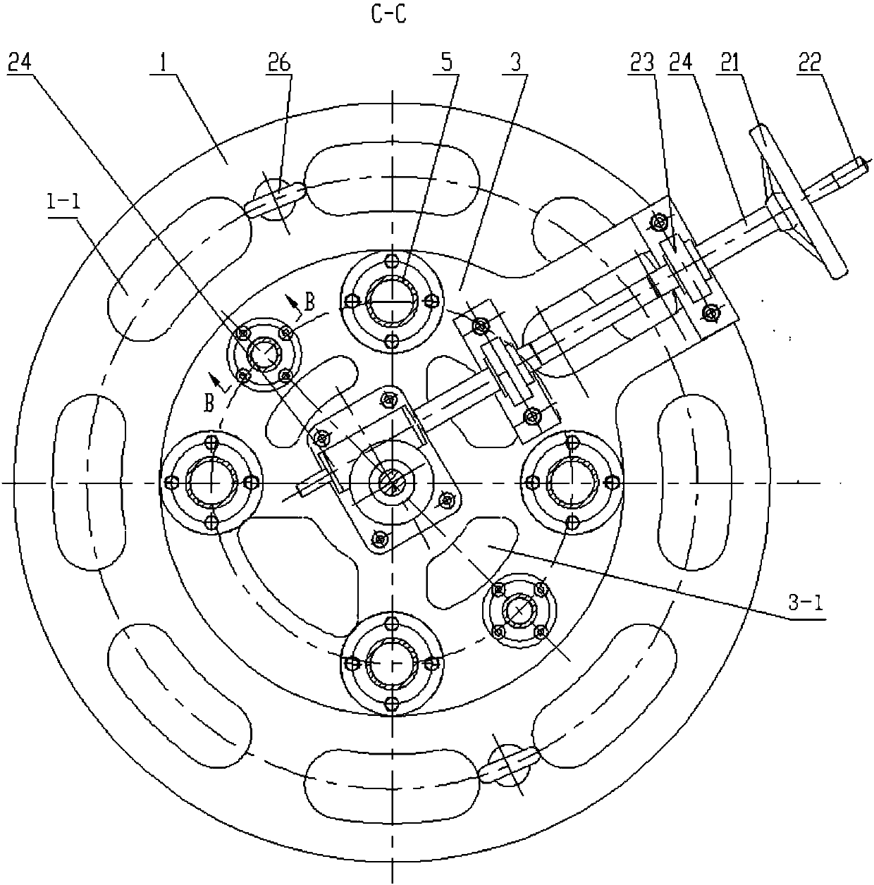
[0048] The base 1 is processed from a steel plate, such as figure 2 , image 3 As shown, the base is provided with a weight-reducing hole 1-1 and two suspension rings 26 are installed, th...

Embodiment 2

[0060] This embodiment uses the overall installation and removal device of the engine turbine blade described in Embodiment 1 and the clamp 7 for clamping the free end of the blade and the pair of backing plates 8 for placing the clamp. figure 1 The turbine blades of the engine shown are installed and removed. The fixture 7 is as Figure 17 As shown, it is composed of a support 7-1, a clamp 7-2 and a side plate 7-3. The clamp 7-2 is provided with a groove combined with the free end of the turbine blade and a combination of the support and the side plate. The stepped pin shaft is installed on the support and connected to the side plate through the stepped pin shaft. The backing plate 8 consists of Figure 15 , Figure 16 The shown four arc-shaped plates with a central angle of 90° are provided with lightening holes 8-1 on the arc-shaped plates. The materials of the clamp 7 and the backing plate 8 are medium carbon steel.

[0061] ⅰ Overall installation operation of turbine...


PUM


Abstract

An integral engine turbine blade mounting and dismounting device comprises a base, a lower column, an upper column, a lifter, a lifter driving assembly, a lifter installing plate, a lifting frame, a lifting frame guiding rod, a lifting frame guiding sleeve, a pull rod, a pull plate, an adapter part, a positioning disc, a turbine disc supporting ring, a blade supporting ring, an assembling compression cover and a detachable compression cover. An integral engine turbine blade mounting and dismounting method comprises the steps that when engine turbine blades are mounted and dismounted by using the device, a clamp for clamping the free ends of the blades and a base plate for the clamp to be placed, a turbine disc and the turbine disc supporting ring are fixedly connected, the turbine disc iskept stationary, the lifter is utilized as a power source, the turbine blades and the assembling compression cover or the detachable compression cover are driven to descend so as to achieve assembly and disassembly of the turbine blades. By using the device and the method, safe, quick and convenient mounting and dismounting of the engine turbine blades can be achieved, assembly and disassembly quality are ensured, and the effect is improved.

Description

technical field [0001] The invention belongs to the field of assembly of engine turbine blades, and in particular relates to a device and method for realizing assembly and disassembly of turbine blades in a mechanical manner. Background technique [0002] In the prior art, the assembly of the turbine blades of the engine is usually completed by manual operation with the help of simple process equipment, that is, the lower end of the turbine disk is supported by a simple bracket, and the tenons of the turbine blades are respectively put into the tenon grooves of the turbine disk, and then the blades are fixed with a rubber hammer. Knock the tenon of each blade to make the tenon of the blade enter the tenon groove of the turbine disk. A similar manual operation is used for turbine blade removal. Since the impact force is generated by the hammer, if the force is not well controlled, it is easy to damage the turbine disk and the tenon of the blade, so the quality of assembly an...

Claims


Application Information

Patent Timeline
Patent Type & Authority Applications(China)
IPC IPC(8): B23P19/04B25B11/02
Inventor 李亚王均肖国郁罗仁俊
Owner CHENGDU ENGINE GROUP
Why Eureka
Try Eureka