Curve segment immersed tube binding jig frame supporting device and supporting method

The technology of a support device and a support method is applied in the field of curved section immersed tube tying tire frame support devices, which can solve the problems that the supports cannot correspond to the fixed beams and cannot support the steel cage, etc., so as to achieve better support, ensure the center of gravity, and good stability sexual effect

Inactive Publication Date: 2018-01-16
CCCC FOURTH HARBOR ENG CO LTD +3
View PDF4 Cites 0 Cited by
  • Summary
  • Abstract
  • Description
  • Claims
  • Application Information

AI Technical Summary

Problems solved by technology

[0005] The purpose of the present invention is to aim at the change of the position of the inner tire frame caused by the change of the lateral position of the segment during the binding process of the immersed tube in the curved section, so that the support for supporting the tire frame base cannot correspond to the fixed beam, resulting in the To solve the problem that the inner tire frame cannot be supported an

Method used


Image

  • Curve segment immersed tube binding jig frame supporting device and supporting method
  • Curve segment immersed tube binding jig frame supporting device and supporting method
  • Curve segment immersed tube binding jig frame supporting device and supporting method

Examples


Embodiment 1

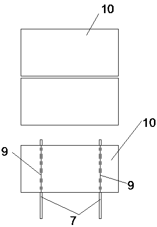
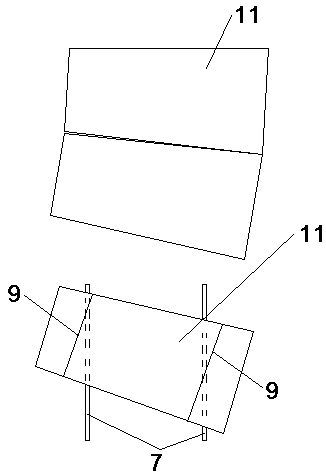
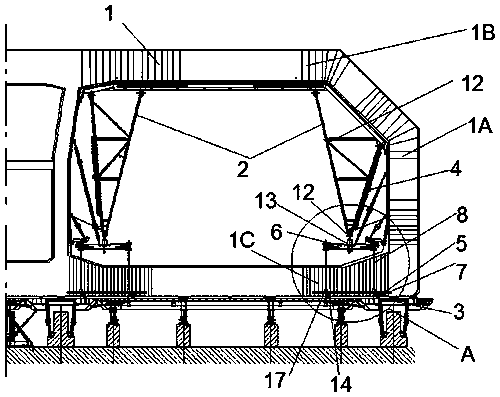
[0054] Such as image 3 , Figure 4 and Figure 5 As shown, the curved section immersed tube binding tire frame support device includes a basic support 12 for supporting the inner tire frame, the bottom of the basic support 12 is provided with a tire frame base 6, and a tire frame base 6 is connected below the tire frame base 6 for supporting the tire frame. The support member 8 of the frame base 6, the below of the support member 8 is provided with a load-sharing beam 5 transversely arranged on the fixed beam 7, and the load-distribution beam 5 extends to the below of the support member 8 along both sides of the fixed beam 7, so that The supporting member 8 can be installed vertically on the load sharing beam 5 .

[0055] At the same time, the reinforcement cage 1 of the immersed tube in the curved section includes wall reinforcement 1A, roof reinforcement 1B and floor reinforcement 1C. In order to ensure sufficient support for the reinforcement cage 1 of the curved section...

Embodiment 2

[0071] Such as image 3 , Figure 4 and Figure 5 As shown, the curved section immersed tube binding tire frame support method specifically includes the following steps:

[0072] a. Install the fixed beam 7, and install the fixed beam 7 on the sliding track 3;

[0073] b. Bind bottom plate reinforcement 1C, bind the lower half of the stirrup and the horizontal and vertical reinforcement of the first layer until it is completed;

[0074] c. Locate the load-sharing beam 5, stake out the load-sharing beam cylinders 17 at the ends of both sides of the immersed tube segment, and determine the positions of the centers of the remaining load-sharing beam cylinders 17 to complete the positioning of the load-sharing beam 5;

[0075] d. Fix the load sharing beam 5 and complete the binding of the bottom plate steel bar 1C;

[0076] e. Install the supporting member 8 , the tire frame base 6 and the tire frame base support 12 .

[0077] By installing the load-sharing beam 5, the gravit...


PUM


Abstract

The invention relates to the technical field of immersed tube tunnels, in particular to a curve segment immersed tube binding jig frame supporting device and supporting method. The curve segment immersed tube binding jig frame supporting method comprises the steps of 1, mounting a fixed beam to a sliding rail; 2, binding a stirrup lower limb of bottom plate steel bars and first layer steel bars inhorizontal and vertical directions; 3, positioning and mounting a load sharing beam, and completing bottom plate steel bar binding; 4, mounting, adjusting and fixing a jig frame basic support. According to the curve segment immersed tube binding jig frame supporting device and supporting method, the load sharing beam is mounted, and therefore the gravity of the jig frame basic support can be vertically conducted to the load sharing beam downwards, and then, the gravity is transmitted to the fixed beam through the load sharing beam, so that the problem is addressed that because the shift of the horizontal position of segments of a curve segment immersed tube, the gravity of the basic support cannot be vertically conducted to the fixed beam downwards, so that it is ensured that the gravitycenter does not deviate, the support of the basic support is more stable, and therefore a curve segment immersed tube binding jig frame is high in stability and does not deform in the process of binding and pushing.

Description

technical field [0001] The invention relates to the technical field of immersed tube tunnels, in particular to a supporting device and a supporting method for a curved section immersed tube binding tire frame. Background technique [0002] The immersed tube tunnel of the Hong Kong-Zhuhai-Macao Bridge is equipped with 33 pipe sections, among which E1~E28 are straight section pipe sections, E29~E33 are curved section pipe sections, and the pipe section plane is located on a circular curve with a radius of 5500m. Curve fitting is carried out with straight instead of curved lines, that is, a single segment is a straight line, and the total length of the curved segment is about 804m. Regardless of whether it is a straight section or a curved section, in the process of binding the steel cage of the immersed tube, in order to speed up the binding progress and achieve the goal of streamlined construction, the steel bar binding work is divided into three work areas: the bottom plate,...

Claims


Application Information

Patent Timeline
IPC IPC(8): E02D29/073
Inventor 张文森黄文慧陈聪朱成周林
Owner CCCC FOURTH HARBOR ENG CO LTD
Why Eureka
Try Eureka