
Codirectional variable-speed transmission coupler and use method

A variable speed transmission and coupling technology, which is applied in the direction of transmission, transmission parts, gear transmission, etc., can solve the problems of no buffering and shock absorption, and cannot change the direction of rotation, etc., and achieve the effect of compact structure and high transmission efficiency

Pending Publication Date: 2018-01-16
CHINA THREE GORGES UNIV
View PDF7 Cites 0 Cited by
  • Summary
  • Abstract
  • Description
  • Claims
  • Application Information

AI Technical Summary

Problems solved by technology

[0002] At present, the widely used mechanical transmission components and couplings can only achieve 1:1 constant speed transmission when transmitting motion and torque, and cannot change the rotation direction of the original shaft, let alone the effect of cushioning and shock absorption.
Ordinary couplings use a single chain connection, which can only play the role of transmission

Method used


Image

  • Codirectional variable-speed transmission coupler and use method
  • Codirectional variable-speed transmission coupler and use method

Examples


Embodiment 1

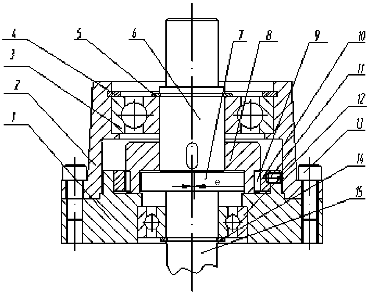
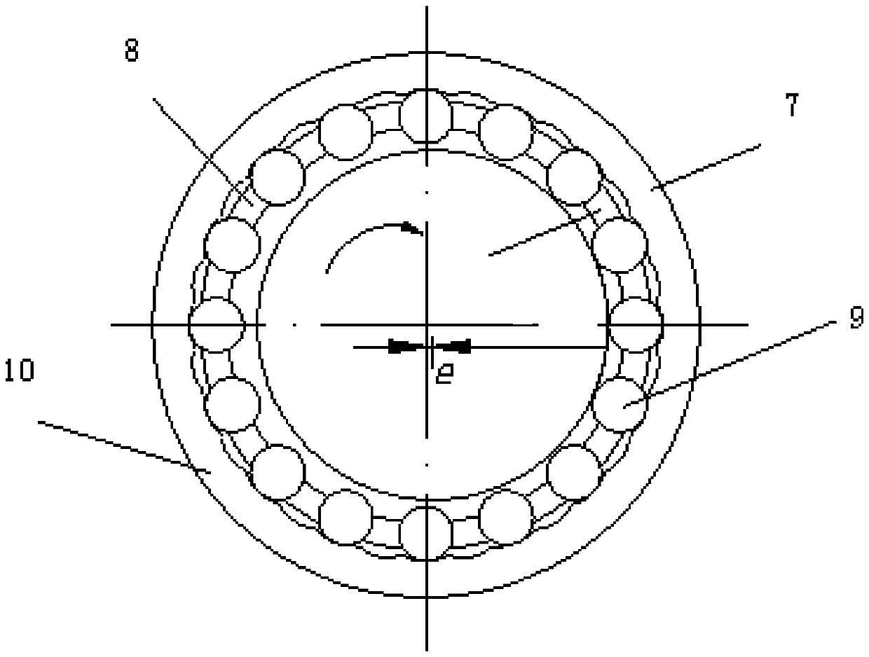
[0021] Such as Figure 1-2 , a transmission coupling with variable speed in the same direction, which includes an input shaft 15, a second rolling bearing 12 is set on the input shaft 15, and an outer ring fastener 1 is set on the outside of the second rolling bearing 12; One end of the ring fastener 1 is provided with a cycloidal tooth 10, and the two are fixed by a locking screw 11; the inner ring of the cycloidal tooth 10 is provided with a middle ring 8, and the middle ring 8 and the cycloidal tooth 10 Cylindrical rollers 9 are installed between them; the eccentric wheel 7 is arranged inside the middle ring 8, and the eccentric wheel 7 is installed on the input shaft 15; the middle ring 8 is installed on the output shaft 6; the output shaft 6 The outer edge of the outer shell 2 is fixedly connected with the middle ring 1 through the hexagonal bolt 13 through the first rolling bearing 3 .

[0022] Further, the output shaft 6 is provided with a first clip spring 5 outside t...

Embodiment 2

[0027] A method of using a co-directional variable speed transmission coupling, using hexagonal bolts 13 to fix the outer ring fastener 1 and the housing 2, and the outer ring fastener 1 fixes the cycloidal teeth 10 through locking screws 11, and finally Fix the cycloid ring gear;

[0028] When the main motion is transmitted from the input shaft 15 to the middle eccentric wheel for input rotation, the cylindrical roller is pushed outward due to the effect of eccentricity. At this time, since the outer cycloidal teeth of the cylindrical roller are fixed, the Under extrusion, the cylindrical roller can only release the interference of this radial movement obstruction by squeezing the fixed cycloidal ring gear to produce a circumferential movement, so that the cylindrical roller has a circular movement, thereby driving The middle ring 8 transmits the circular motion to the output shaft;

[0029] When the shaft of the middle eccentric wheel rotates a circle, the eccentric wheel s...


PUM


Abstract

The invention discloses a codirectional variable-speed transmission coupler and a use method. The codirectional variable-speed transmission coupler comprises an input shaft, wherein the input shaft issleeved with a second rolling bearing, the outside of the second rolling bearing is sleeved with an outer ring fastener, cycolidal teeth are arranged in the inner cavity of one end of the outer ringfastener, and the cycolidal teeth and the outer ring fastener are fixed through locking screws. A middle ring is arranged in the middle of the cycolidal teeth, and cylindrical rollers are installed between the middle ring and the cycolidal teeth. An eccentric wheel is arranged in the middle ring, and installed on the input shaft. The middle ring is installed on the output shaft. A housing for matching is installed on the output shaft through a first rolling bearing. The outer edge of the housing is fixedly connected with the middle ring through hexagon bolts. The coupler can achieve the functions of a traditional clutch, can also provide different transmission ratios, or even can play the positioning and supporting effects of the bearings.

Description

technical field [0001] The invention relates to a co-direction variable speed transmission coupling and its use method, in particular to a transmission device capable of realizing speed-up, constant-speed and speed-down. Background technique [0002] At present, the widely used mechanical transmission components and couplings can only achieve 1:1 constant speed transmission when transmitting motion and torque, and cannot change the rotation direction of the original shaft, let alone have the effect of cushioning and shock absorption. The ordinary coupling adopts a single chain connection, which can only play the role of transmission. Contents of the invention [0003] The present invention aims to overcome the shortcomings of the above-mentioned prior art, and provides a co-directional variable speed transmission coupling and its use method. This coupling can not only realize the function of the traditional clutch, but also provide different transmission ratios, even It c...

Claims


Application Information

Patent Timeline
Patent Type & Authority Applications(China)
IPC IPC(8): F16H1/32F16H57/00F16H57/08F16C3/22
Inventor 张发军宋钰青邓安禄
Owner CHINA THREE GORGES UNIV
Learn More