
Assembly method for camera system suitable for mobile terminal

A technology of a camera system and an assembly method, which is applied in the parts, installation, image communication and other directions of a TV system, can solve problems such as working distance, stray light, and increase the design difficulty of the imaging lens group after the imaging lens group is long, so as to improve the complexity of the imaging lens group. Astigmatism problem, improved optical performance, effect of short back focus

Inactive Publication Date: 2018-01-16
GALAXYCORE SHANGHAI
View PDF7 Cites 6 Cited by
  • Summary
  • Abstract
  • Description
  • Claims
  • Application Information

AI Technical Summary

Problems solved by technology

This requires the imaging lens group to have a relatively long rear working distance (the distance between the last piece of the imaging lens group and the photosensitive surface of the image sensor chip), which will increase the design difficulty of the imaging lens group for ultra-thin modules, which is not conducive to improving Imaging performance of the camera module
In addition, the infrared cut filter not only reduces the transmittance of the camera module, but also easily causes the problem of stray light in the process of taking pictures

Method used


Image

  • Assembly method for camera system suitable for mobile terminal
  • Assembly method for camera system suitable for mobile terminal
  • Assembly method for camera system suitable for mobile terminal

Examples


no. 1 example

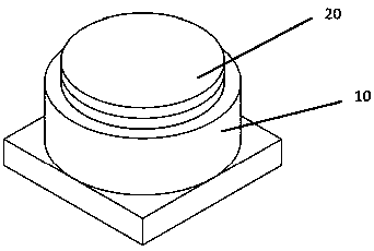
[0028] figure 1 It is a schematic diagram of the three-dimensional structure of the camera system according to the present invention.

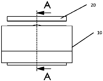
[0029] Figure 2a is a schematic side view of the camera system according to the first embodiment of the present invention.

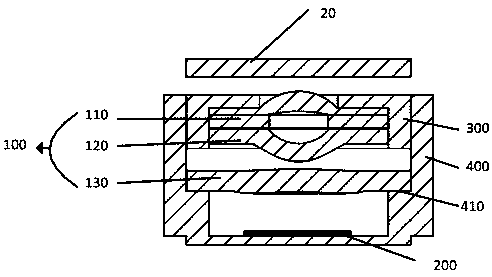
[0030] Figure 2b yes Figure 2a A side sectional view along the A-A direction;

[0031] image 3 It is a schematic cross-sectional view of the imaging lens group and the lens group sleeve in the imaging system of the first embodiment of the present invention;

[0032] Figure 4 It is a schematic cross-sectional view of the image sensor packaging module in the camera system of the first embodiment of the present invention;

[0033] Please refer to figure 1 , the camera system includes a camera module 10 and a protective cover 20 of the camera system, please refer to Figure 2a , Figure 2b , The camera module 10 includes: a lens group 100, an image sensor chip 200, the camera module 10 can be a fixed-focus cam...

no. 2 example

[0035] Figure 5a It is a schematic side view of the camera system according to the second embodiment of the present invention.

[0036] Figure 5b yes Figure 5a A side sectional view along the A-A direction;

[0037] Figure 6 It is a schematic cross-sectional view of the imaging lens group and the lens group sleeve in the camera system of the second embodiment of the present invention;

[0038] Figure 7 is a schematic cross-sectional view of the image sensor packaging module in the camera system according to the second embodiment of the present invention.

[0039] Please refer to Figure 5a , Figure 5b, the camera system includes a camera module 10' and a protective cover 20' of the camera system. The camera module includes: a lens group 100', an image sensor chip 200', a VCM module 600 located inside a frame 400' around the lens group 100', The VCM module 600 is provided with a VCM motor, and the camera module can be a fixed-focus camera module or an auto-focus c...


PUM


Abstract

The invention proposes an assembly method for a camera system suitable for a mobile terminal, and the camera system comprises a transparent protection cover plate with an infrared cutoff function, a lens group, and an image sensor chip. The method comprises the step: assembling the last lens of the lens group and the image sensor chip into one body, wherein the lens and the image sensor chip forma cavity. The last lens is used for replacing optical glass and / or infrared filter on an image sensor chip in conventional packaging, and the distance between the last lens and an image sensor is therear working distance of the lens.

Description

technical field [0001] The invention relates to an assembly method of a camera system, in particular to an assembly method of a camera system suitable for a mobile terminal. Background technique [0002] The camera system consists of a camera module and other accessories (such as a protective cover on the camera module). The camera module consists of an image sensor chip and an imaging system. The imaging system consists of an imaging lens group, an infrared filter, and an imaging lens. The group is placed in the lens barrel of the module, and the organic cooperation between the position of the lens barrel and the image sensor chip can obtain high-quality images or videos. Hand-held devices, such as mobile phones, laptops, Pads, etc., are developing towards ultra-thin and high-pixel camera modules. The height of the module is getting lower and lower, and the area array of the image sensor chip is getting bigger and bigger, and the pixel size is getting smaller and smaller. ...

Claims


Application Information

Patent Timeline
IPC IPC(8): G02B7/00G02B7/02G02B7/04H04N5/225
Inventor 赵立新杜柯侯欣楠
Owner GALAXYCORE SHANGHAI
Learn More