Cable duct threading traction device

A cable duct and traction device technology, applied in cable laying equipment and other directions, can solve the problems of high labor intensity, difficult construction, poor versatility, etc., and achieve the effects of improving threading time, ensuring traction, and being simple and convenient to use.

Active Publication Date: 2020-11-17
宝应帆洋船舶电器配件制造有限公司
View PDF8 Cites 2 Cited by
  • Summary
  • Abstract
  • Description
  • Claims
  • Application Information

AI Technical Summary

Problems solved by technology

[0002] At present, in the home decoration, or in the electrical engineering installation process of various buildings, in order to make the indoor environment beautiful and generous, various power lines, telephone lines, network lines, TV signal lines and various lines of the audio system are buried by hidden pipes. , put the iron wire in the pipe first, then pre-embed the pipe in the brick wall or concrete wall, finally tie the iron wire on the end of the wire, and put the wire into the pipe. The disadvantage: the labor intensity is high, once the wire is stuck or the wire To get off the wire, people have to cut open the stuck place and destroy the original structure. At present, high-pressure airflow is also used to make the pipe plug in the pipe to drive the wire to move forward. The disadvantage is that the diameter of the pipe plug must match the inner diameter of the pipe, which is universal. It is poor, and it is more difficult to construct where the pipe is bent, so we need a pipe pulling device that can adapt to the height and can be threaded easily and quickly

Method used


Image

  • Cable duct threading traction device
  • Cable duct threading traction device
  • Cable duct threading traction device

Examples


Embodiment Construction

[0020] The technical solutions in the embodiments of the present invention will be clearly and completely described below in conjunction with the accompanying drawings in the embodiments of the present invention. Obviously, the described embodiments are only a part of the embodiments of the present invention, rather than all the embodiments. Based on the embodiments of the present invention, all other embodiments obtained by those of ordinary skill in the art without creative work shall fall within the protection scope of the present invention.

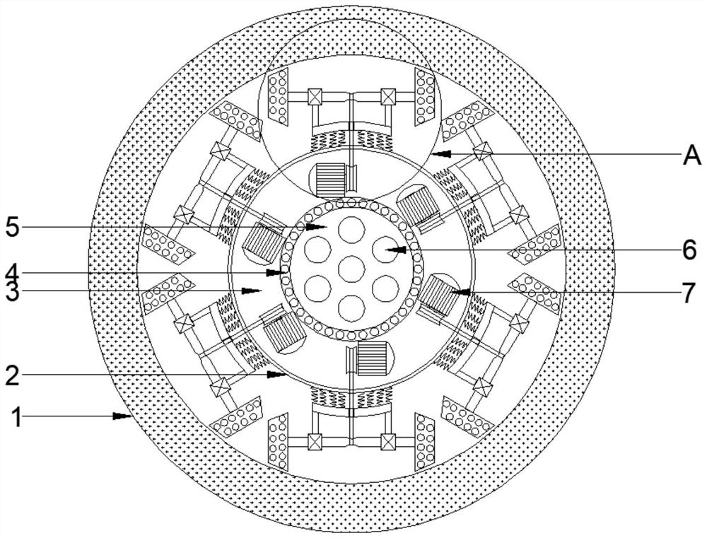
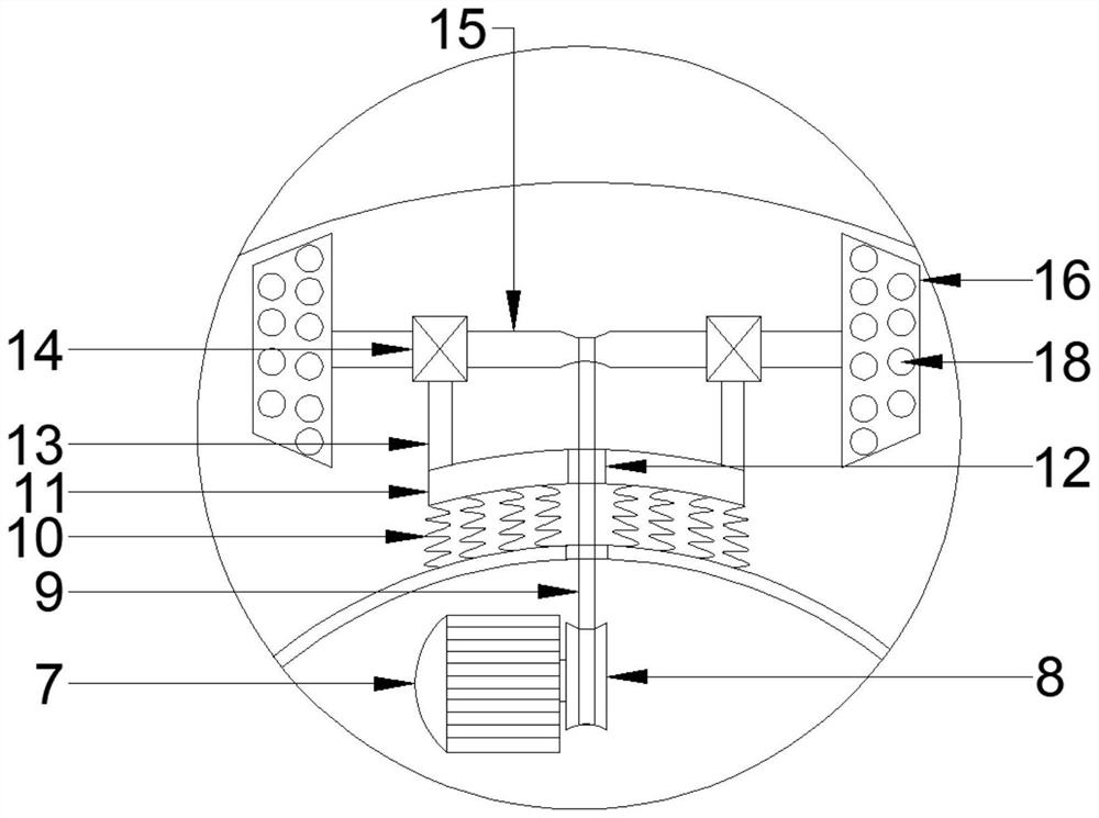
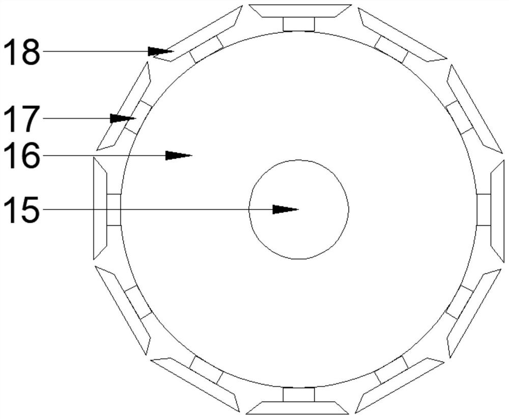
[0021] See Figure 1~6 In the embodiment of the present invention, a cable duct threading and traction device includes a cable tube 1, a round table base 2, a motor room 3, a spool bearing 4, a cable fixing plate 5, a cable hole 6, a drive motor 7, a roller 8. Belt 9, support spring 10, support plate 11, belt hole 12, support frame 13, support bearing 14, drive shaft 15, drive wheel 16, suction cup bracket 17, suction cup 18, buckle fixi...


PUM


Abstract

The invention discloses a cable pipeline threading traction apparatus. The cable pipeline threading traction apparatus comprises a circular table base; a motor room is arranged in the circular table base; multiple driving motors are arranged in the motor room; a rolling wheel is fixed on a motor rotary shaft; the rolling wheel is connected with a driving rotary shaft through a belt; supporting springs are arranged between a supporting plate and the circular table base; driving wheels are fixed at the two ends of the driving rotary shaft; multiple suction cup brackets are fixed on the surfacesof the driving wheels; a cable fixing plate is arranged on the inner side of the motor room; a wire tray bearing is mounted between the cable fixing plate and the motor room; multiple cable holes areformed in the cable fixing plate; buckle fixing blocks are arranged on the two sides of the circular holes of the cable holes; cable buckles are arranged on the inner sides of the buckle fixing blocks; multiple lithium battery panels are mounted on the back surface of the circular table base; the lithium battery panels are electrically connected with a control box through power lines; and a relay,a rotary knob switch and a charging port are arranged in the control box. The cable pipeline threading traction apparatus, driven by the motors, can complete threading of multiple cables at the sametime.

Description

Technical field [0001] The invention relates to the field of traction devices, in particular to a cable duct threading traction device. Background technique [0002] At present, in the process of home decoration or the installation of electrical engineering of various buildings, in order to make the indoor environment beautiful and generous, all kinds of power lines, telephone lines, network lines, TV signal lines and various lines of the sound system are buried in concealed pipes. , First put the iron wire in the pipe, then pre-bury the pipe in the brick wall or concrete wall, finally tie the iron wire to the end of the wire, and put the wire into the pipe. The disadvantage: labor intensity is high, once the wire is stuck or the wire When the wire is disconnected, people have to dig out the stuck place and destroy the original structure. At present, high-pressure airflow is also used to make the pipe plug in the pipe to drive the wire forward. The disadvantage is that the diamet...

Claims


Application Information

Patent Timeline
Patent Type & Authority Patents(China)
IPC IPC(8): H02G1/08
Inventor 黄根太
Owner 宝应帆洋船舶电器配件制造有限公司
Why Eureka
Try Eureka