
Pin cutting device for electronic element

A technology for cutting legs of electronic components, which is applied in the field of cutting devices for electronic components, can solve the problems of complex structure, difficult cost, high manufacturing cost, etc., and achieve the effects of simple overall structure, low manufacturing cost, and low input cost

Inactive Publication Date: 2018-01-19
张义英
View PDF5 Cites 3 Cited by
  • Summary
  • Abstract
  • Description
  • Claims
  • Application Information

AI Technical Summary

Problems solved by technology

[0002] In the production process of some electronic components, it is usually necessary to partially cut off the pins of the electronic components, so as to facilitate the insertion and soldering of the electronic components on the circuit board during the process of fixing the electronic components to various circuit boards. , and avoid the process of cutting off the long pins after soldering, so as to improve the efficiency and automation of circuit board processing; but the current cutting pins have complex structures and high manufacturing costs. For some small and medium-sized enterprises, It is difficult to invest too much cost; therefore, in order to solve the above problems, a cutting device for electronic components is needed

Method used


Image

  • Pin cutting device for electronic element

Examples


Embodiment Construction

[0012] The present invention will be further described below in conjunction with the accompanying drawings.

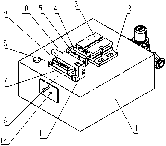
[0013] Such as figure 1 As shown, a cutting device for electronic components includes a bottom box 1, electronic components and solenoid valves are housed in the bottom box 1, the upper end of the bottom box 1 is provided with a cylinder mounting plate 2, and the upper end of the cylinder mounting plate 2 is There is a cutting cylinder 3, which drives the guide plate 4 to move, thereby driving the cutting knife 5 to realize the cutting function. The front end of the cutting cylinder 3 is provided with a guide plate 4, and the upper end of the guide plate 4 is provided with a cutting plate. Cutter 5, the vertical part of cutter 5 and guide plate 4 is connected with spring, plays buffering effect, described cylinder mounting plate 2 front is provided with seat plate 6, and described seat plate 6 upper end is provided with support plate 7, supports There is a square groo...


PUM


Abstract

The invention discloses a pin cutting device for an electronic element. The pin cutting device comprises a bottom box, wherein the upper end of the bottom box is provided with an air cylinder installing plate; the upper end of the air cylinder installing plate is provided with a cutting air cylinder; the front end of the cutting air cylinder is provided with a guide plate; the upper end of the guide plate is provided with a cutting knife; a seat plate is arranged in front of the air cylinder installing plate; the upper end of the seat plate is provided with a support plate; the upper end of the support plate is provided with a cutting plate; the upper end of the cutting plate is provided with a placing plate; a press plate is arranged above the placing plate; the right end of the press plate is provided with a support seat; a dust gathering box is arranged on a front side plate of the bottom box. Generally, the pin cutting device has the advantages that the structure is simple; the investment cost is low.

Description

technical field [0001] The invention relates to the technical field of electronic component processing equipment, in particular to a leg cutting device for electronic components. Background technique [0002] In the production process of some electronic components, it is usually necessary to partially cut off the pins of the electronic components, so as to facilitate the insertion and soldering of the electronic components on the circuit board during the process of fixing the electronic components to various circuit boards. , and avoid the process of cutting off the long pins after soldering, so as to improve the efficiency and automation of circuit board processing; but the current cutting pins have complex structures and high manufacturing costs. For some small and medium-sized enterprises, It is more difficult to invest too much cost; therefore, in order to solve the above problems, a cutting device for electronic components is needed. Contents of the invention [0003...

Claims


Application Information

Patent Timeline
Patent Type & Authority Applications(China)
IPC IPC(8): B21F11/00
Inventor 张义英
Owner 张义英
Learn More