Eureka AIR delivers breakthrough ideas for toughest innovation challenges, trusted by R&D personnel around the world.

A three-way multi-stage energy-absorbing device for rail vehicles

A rail vehicle and energy-absorbing device technology, which is applied in the direction of railway vehicle wheel guards/buffers, transportation and packaging, railway car body parts, etc., can solve problems such as small energy absorption capacity, deformation instability, and reduced resistance , to achieve the effect of large energy absorption capacity, compact structure and small impact force

Active Publication Date: 2019-03-29
CHENGDU GUOJIA ELECTRICAL ENG CO LTD
View PDF6 Cites 0 Cited by
  • Summary
  • Abstract
  • Description
  • Claims
  • Application Information

AI Technical Summary

Problems solved by technology

When the crushed structure absorbs energy, the resistance fluctuates greatly, and it is prone to deformation and instability, and the resistance will suddenly decrease and lose the energy absorption capacity.
[0005] Expansion-type energy-absorbing devices mainly include pipe expansion and gas expansion, and it is difficult to effectively control the range of energy absorbed by them when a collision occurs, and cannot overcome the shortcomings of low resistance level and small energy-absorbing capacity
[0006] Through the above analysis, it can be found that the existing energy-absorbing structures have their own advantages and disadvantages. The biggest problem is the ability to overcome resistance and improve the level of stability of resistance.

Method used


Image

  • A three-way multi-stage energy-absorbing device for rail vehicles
  • A three-way multi-stage energy-absorbing device for rail vehicles
  • A three-way multi-stage energy-absorbing device for rail vehicles

Examples


Embodiment Construction

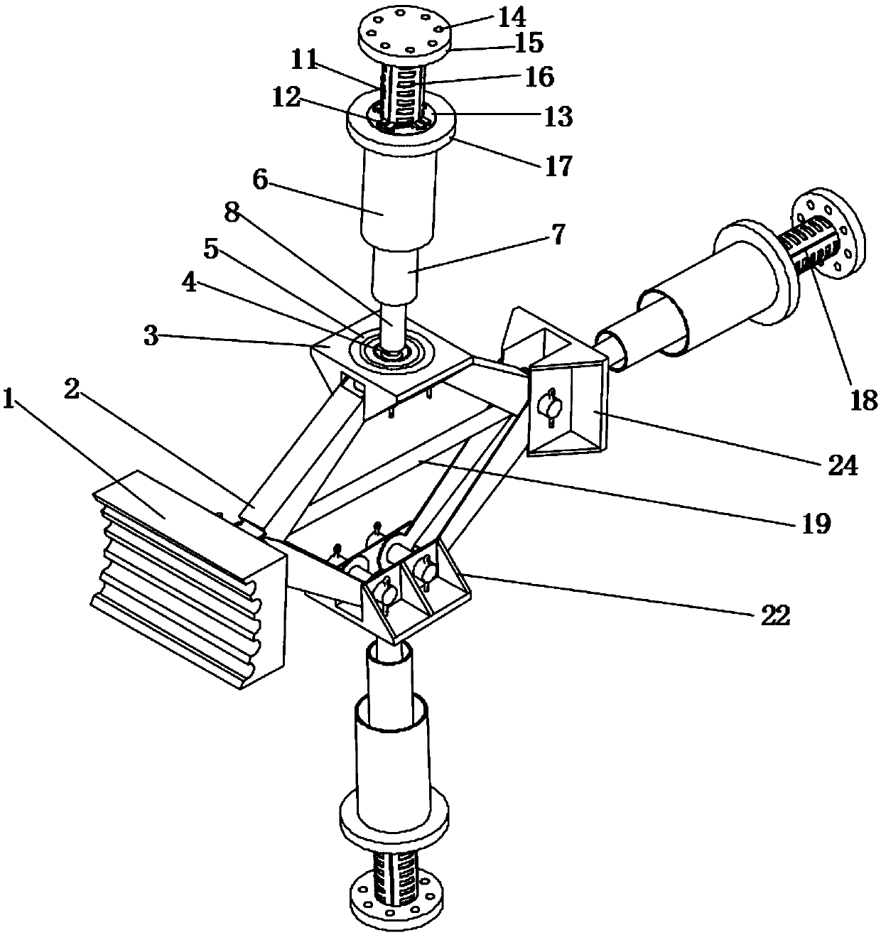
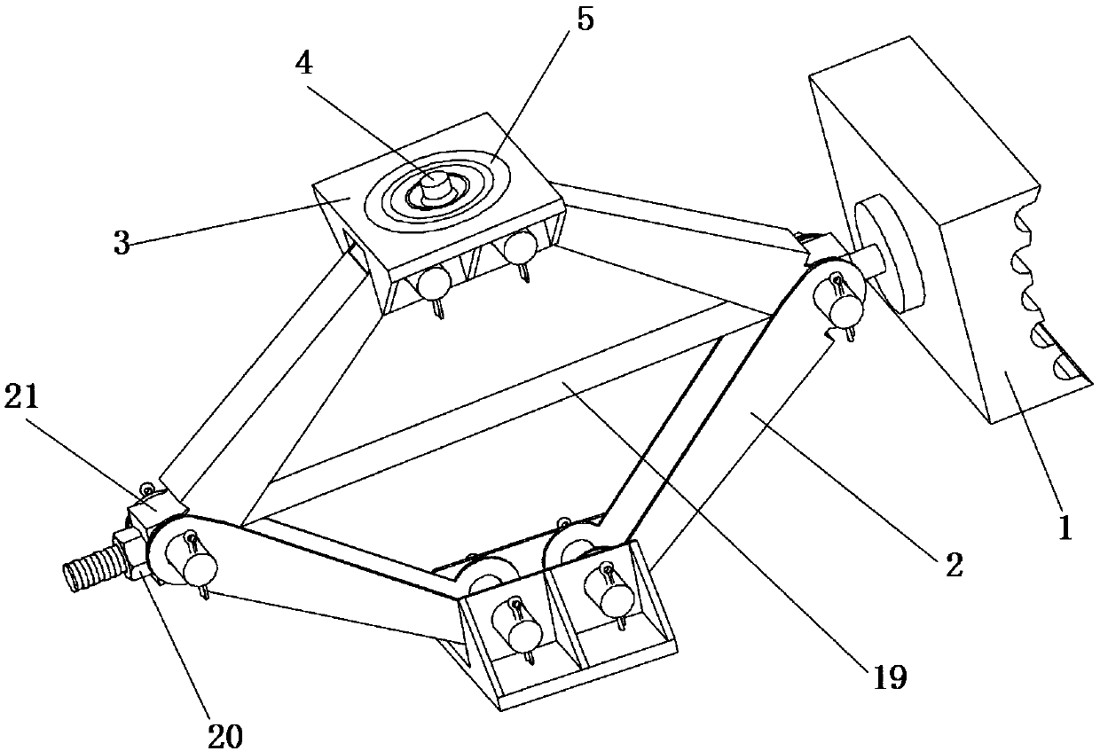
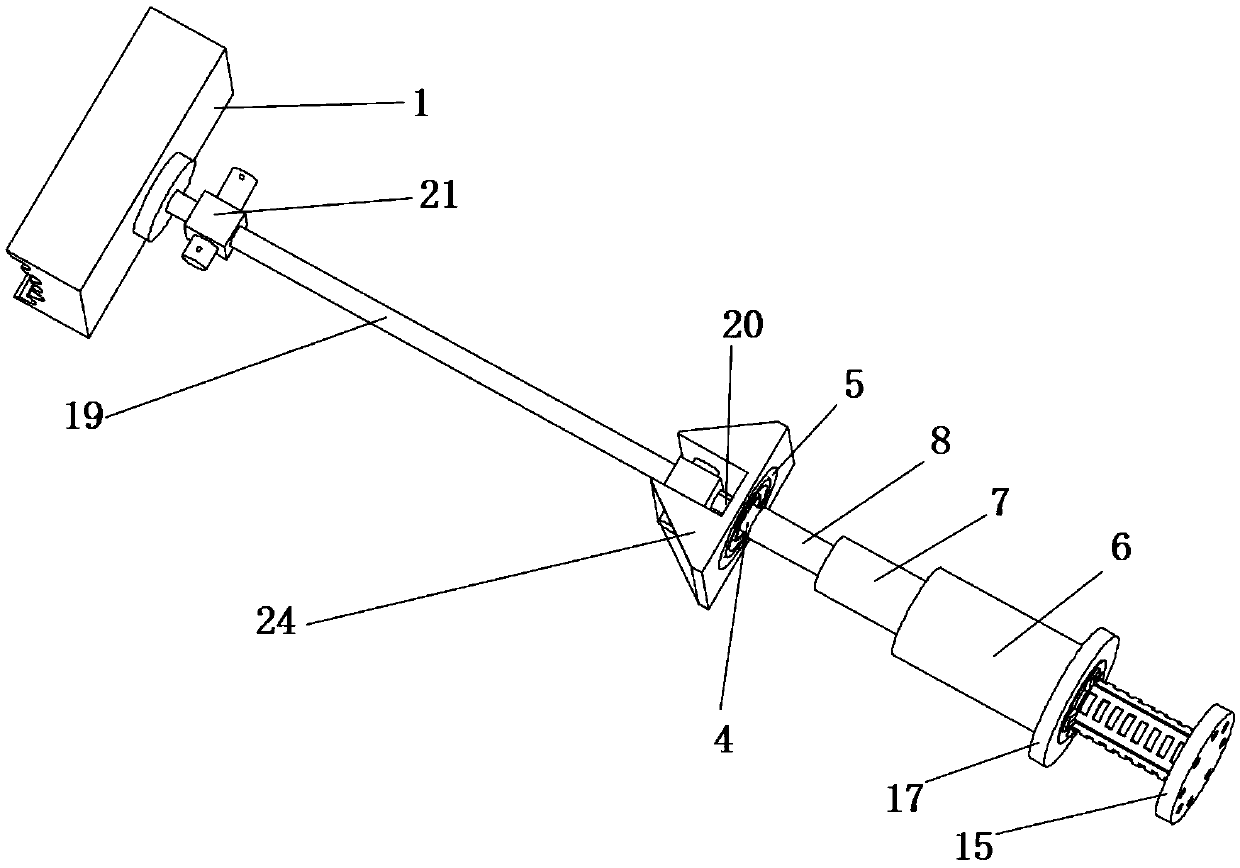
[0029] Such as figure 1 As shown, a three-way multi-stage energy-absorbing device for a rail vehicle includes an anti-climber 1, a bracket 2, an energy-absorbing pipe 8 and a cutting shaft 9; the anti-climber 1 is connected to one end of a screw 19; the other end of the screw 19 passes through The hole and the induction ring 23 of the boss 21 in the single-hole top block 24 are limited by the nut 20; the bracket 2 is hinged by a bolt to form a parallelogram structure; the double-hole top block 3 or the single-hole top block 24 is connected to the bracket 2 and the first energy-absorbing tube 8, the two sides of the top block are provided with reinforcing ribs 22, the back end of the double-hole top block 3 is provided with a rolling groove 5 and the induction platform 4, and the back end of the single-hole top block 24 is provided with an induction ring 23; the energy-absorbing tube One end of 8 is interference fit with the induction table 4; one end of the energy-absorbing tu...


PUM


Abstract

The invention provides a three-direction multi-stage energy absorption device for a railway vehicle and belongs to the technical field of passive safety of rail traffic vehicles. A screw with an anti-creeper penetrates through through-holes of two bosses and an induction ring in the center of a single-hole pushing block. The two ends of four supporting arms are hinged to pushing blocks through bolt pins to form a support of a parallelogram structure. The back end face of each pushing block is provided with a turnup groove and one induction ring and fixedly connected with first energy absorption pipes. The back end face of each pushing block is provided with one turnup groove. Each first energy absorption pipe, each second energy absorption pipe and each third energy absorption pipe are each provided with a cutting head, wherein each cutting head is axially embedded in one end of another energy absorption pipe. Inner rings of the cutting heads are in threaded connection with small endsof cutting shafts combined with the cutting heads correspondingly, cutter mounting seats and W-shaped cutters are arranged at the end faces of the cutting heads, and sharp knives of the W-shaped cutters are located in induction grooves. The cutting shafts are stepped shafts, and the lateral surfaces of the cutting shafts are provided with the induction grooves and threads at intervals. The three-direction multi-stage energy absorption device for the railway vehicle is used for passive safety of the vehicle.

Description

technical field [0001] The invention belongs to the technical field of passive safety of rail transit vehicles, and relates to the passive safety technology of train ends. Background technique [0002] In recent years, with the rapid development of my country's high-speed railways, the requirements for high-speed trains and lightweight trains have become higher and higher. While the speed has increased and the quality has decreased, the safety of trains has also attracted more and more attention from the industry. Among them The passive safety performance of trains is of particular concern. The energy-absorbing anti-climbing device is an important part of the passive safety of rail trains. Its main function is to absorb the collision energy of the vehicle end through the energy-absorbing anti-climbing device when the rolling stock inevitably collides, reduce the impact of the vehicle, and protect the passengers to the greatest extent. To ensure the safety of personnel and on...

Claims


Application Information

Patent Timeline
Patent Type & Authority Patents(China)
IPC IPC(8): B61F19/04
Inventor 杨龙阳光武肖守讷杨冰朱涛
Owner CHENGDU GUOJIA ELECTRICAL ENG CO LTD
Why Eureka
Eureka Blog
Learn More