Eureka AIR delivers breakthrough ideas for toughest innovation challenges, trusted by R&D personnel around the world.

Pressing-proof type universal ball device

A technology of anti-pressure and movable plate, which is applied in the direction of transportation and packaging, conveyor objects, rollers, etc., can solve the problems of universal ball deformation, displacement and damage, reduce transmission efficiency, and reduce the service life of universal ball devices, etc., to achieve Reduce the cost of use and maintenance, improve the overall pressure resistance, and improve the service life

Pending Publication Date: 2018-01-19
湖州吴兴锐质自动化输送设备厂(普通合伙)
View PDF14 Cites 5 Cited by
  • Summary
  • Abstract
  • Description
  • Claims
  • Application Information

AI Technical Summary

Problems solved by technology

The universal ball devices currently used are simple universal ball transmission, which does not involve the compressive capacity of the universal ball, so that the universal ball is often deformed, displaced and damaged during the transmission of large or heavy items. The phenomenon seriously affects the normal use of the transmission device, reduces the service life of the universal ball device, reduces the transmission efficiency, requires regular maintenance and replacement by maintenance personnel, and increases the use cost of the automatic transmission equipment
[0003] To sum up, the existing universal ball device still has great defects in structure and design, and cannot meet the needs of modern efficient production

Method used


Image

  • Pressing-proof type universal ball device
  • Pressing-proof type universal ball device

Examples


Embodiment Construction

[0018] In order to make the technical problems, technical solutions and beneficial effects solved by the present invention clearer, the present invention will be further described in detail below in conjunction with the accompanying drawings and embodiments. It should be understood that the specific embodiments described here are only used to explain the present invention, not to limit the present invention.

[0019] In the description of the present invention, it should be understood that the terms "one side", "the other side", "both sides", "middle", "inside", "upper end", "lower end", "upper" The orientation or positional relationship indicated by , "lower", etc. is based on the orientation or positional relationship shown in the drawings, and is only for the convenience of describing the present invention and simplifying the description, rather than indicating or implying that the referred device or element must have a specific orientation , constructed and operated in a p...


PUM


Abstract

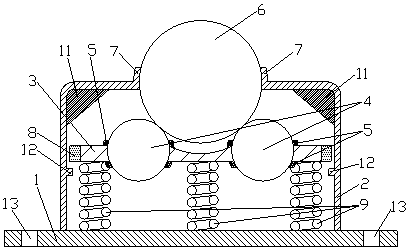
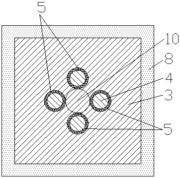
The invention relates to the technical field of automation conveying equipment, in particular to a pressing-proof type universal ball device. The pressing-proof type universal ball device is providedwith a base, a shell is fixedly arranged at the upper end of the base, a movable plate is horizontally arranged in the shell, and the base is connected with the lower end of the movable plate in an elastic mode; a plurality of rolling steel balls are arranged in the middle of the movable plate in a nested mode, ring-shaped fixing sleeves are arranged at the position of the rolling steel balls andthe upper end surface as well as the lower end surface of the movable plate, a square structure is enclosed by the rolling steel balls, and a universal ball is arranged on the square structure; and the upper portion of the universal ball penetrates out of the upper end surface of the shell, and a universal ball positioning sleeve is arranged between the universal ball and the upper end surface ofthe shell. According to pressing-proof type universal ball device, the structure is simple, the overall anti-pressing ability of the universal ball device can be improved, the service life is prolonged, the using and maintenance cost is reduced, and the whole automation transmission efficiency is improved.

Description

technical field [0001] The invention relates to the technical field of automatic conveying equipment, in particular to a pressure-proof universal ball device. Background technique [0002] With the development of society, the automatic transmission equipment industry has developed rapidly. Automatic transmission equipment includes rollers, fluent strips, universal balls, etc. Universal balls are a transmission device that can be adjusted and changed in reverse. The key to the transmission of the universal ball device lies in the rolling of the universal ball to drive the items on the universal ball for transmission. The universal ball devices currently used are simple universal ball transmission, which does not involve the compressive capacity of the universal ball, so that the universal ball is often deformed, displaced and damaged during the transmission of large or heavy items. The phenomenon seriously affects the normal use of the transmission device, reduces the servi...

Claims


Application Information

Patent Timeline
IPC IPC(8): B65G13/00B65G39/02B65G39/14
Inventor 邱立志杨沪生
Owner 湖州吴兴锐质自动化输送设备厂(普通合伙)
Why Eureka
Eureka Blog
Learn More