Conveyor chain automatic start-stop control method based on section steel conveyor chain control system

A control system and control method technology, applied in the direction of conveyor control devices, conveyors, conveyor objects, etc., can solve the problems of mobile position detection encoder failure, poor working environment, etc., to solve frequent failures and ensure stable and smooth operation. line effect

Active Publication Date: 2019-07-02
MAANSHAN IRON & STEEL CO LTD
View PDF7 Cites 0 Cited by
  • Summary
  • Abstract
  • Description
  • Claims
  • Application Information

AI Technical Summary

Problems solved by technology

[0003] The embodiment of the present invention provides an automatic start-stop control method for the conveyor chain based on the section steel conveyor chain control system, aiming to solve the problem that the 3# conveyor chain dynamic position detection rotary encoder is installed on the non-drive side shaft of the 3# conveyor chain drive motor. The working environment is very harsh, which leads to the frequent failure of the mobile position detection encoder

Method used


Image

  • Conveyor chain automatic start-stop control method based on section steel conveyor chain control system
  • Conveyor chain automatic start-stop control method based on section steel conveyor chain control system

Examples


Embodiment Construction

[0011] In order to make the object, technical solution and advantages of the present invention clearer, the present invention will be further described in detail below in conjunction with the accompanying drawings and embodiments. It should be understood that the specific embodiments described here are only used to explain the present invention, not to limit the present invention.

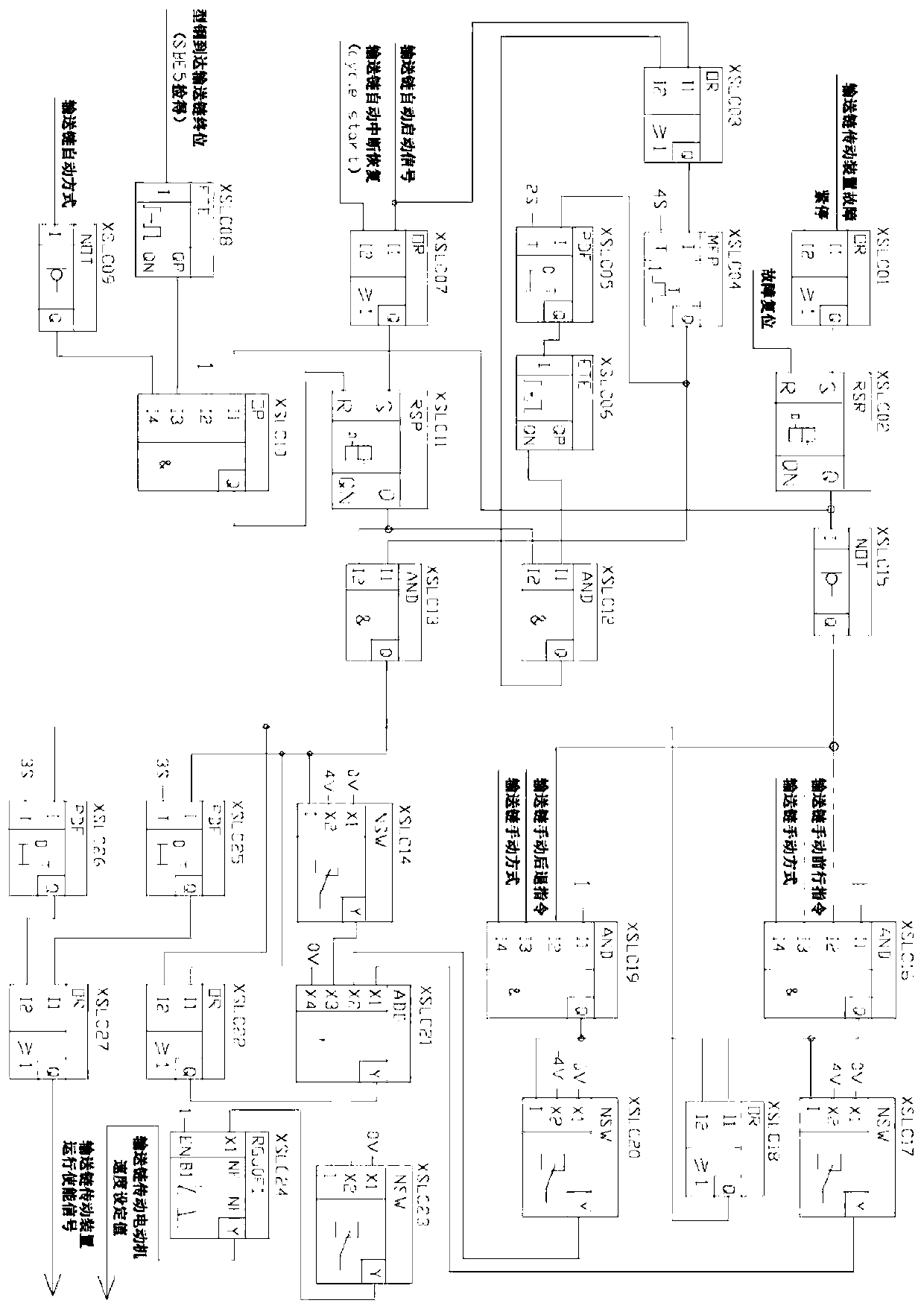
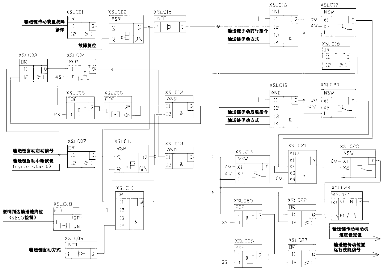
[0012] figure 1 It is a structural schematic diagram of the 3# conveyor chain control system of the section steel inspection platform provided by the embodiment of the present invention. For the convenience of description, only the parts related to the present invention are shown.

[0013] Such as figure 1 As shown, NSW is a "digital input switch" function block, when I='1', Y=X2, when I='0', Y=X1; RSR is an RS flip-flop with "reset terminal R priority" "Function block, when S is '1', R is '0', Q is '1', QN is '0', when S is '1', R is '1', Q is '0', QN is '1', when S is '0' and R is '0', Q and Q...


PUM


Abstract

The invention provides an automatic conveyor chain start / stop control method based on a profile steel conveyor chain control system. The automatic conveyor chain start / stop control method is applicable to the technical field of electrical drive control. According to the method, the automatic start / stop control over the advancing step pitch of a conveyor chain is achieved through a circulatory-pulse generator under different duty ratios, automatic start / stop control over the advancing step pitch of the conveyor chain is achieved under the condition of not using a conveyor chain moving positiondetection encoder, the problem that the conveyor chain moving position detection encoder frequently fails due to the poor working environment is solved, and the stable operation of a large H-shaped steel production line is guaranteed.

Description

technical field [0001] The invention belongs to the technical field of electric drive control and provides an automatic start-stop control method for a conveyor chain based on a section steel conveyor chain control system. Background technique [0002] There are three sections of conveyor chains (namely 1#, 2# and 3# conveyor chains) in the large H-beam inspection bench area of ​​Masteel, and each section of conveyor chain is driven by an independent motor. Among them, the 1# and 2# conveyor chains adopt the speed control method, that is, the conveyor chain will move forward according to the set speed after starting, and start to decelerate and stop until the conveyed section steel rolling piece is detected by the ultrasonic detection switch (SBE5), based on Therefore, considering that the conveyor chain does not require high speed accuracy, the speed control of 1# and 2# conveyor chains can be operated without a speed detection encoder. The chain needs to use a vernier cal...

Claims


Application Information

Patent Timeline
Patent Type & Authority Patents(China)
IPC IPC(8): B65G17/38B65G43/00
Inventor 叶光平汪志远徐洪吴卫华
Owner MAANSHAN IRON & STEEL CO LTD
Why Eureka
Try Eureka