Conveying mechanism suitable for plates with different widths

A conveying mechanism and plate technology, applied in conveyors, mechanical conveyors, transportation and packaging, etc., can solve the problems of substandard plate quality, poor adaptability, poor edge sealing effect, etc., and achieve material cost saving, good rolling effect, The effect of high conveying efficiency

Pending Publication Date: 2018-01-19
浙江云峰莫干山家居用品有限公司
View PDF6 Cites 8 Cited by
  • Summary
  • Abstract
  • Description
  • Claims
  • Application Information

AI Technical Summary

Problems solved by technology

[0002] At present, in the home furnishing industry, after the sawing of the board is completed, for subsequent use, an edge banding machine is usually used to seal the sawn board. The current edge banding process is highly mechanized. In order to improve the edge banding Efficiency requires the use of conveying equipment to continuously send the boards that need to be edge-banded to the edge-banding machine. The existing conveying equipment that sends the boards to the edge-banding machine usually simply uses a motor to drive the gear to drive the conveyor belt to rotate. The plate is rotated to be sent to the edge banding machine for edge banding. No matter what width the plate is, the same conveying equipment is used uniformly, which has poor adaptability. When it is necessary to transport the plate with a larger or smaller width, it cannot The specific width of the board is adjusted accordingly, which cannot better cooperate with the edge banding work of the edge banding machine, resulting in poor edge banding effect, and the quality of the board after edge banding is prone to be substandard

Method used


Image

  • Conveying mechanism suitable for plates with different widths
  • Conveying mechanism suitable for plates with different widths
  • Conveying mechanism suitable for plates with different widths

Examples


Embodiment Construction

[0017] The present invention will be further described below in conjunction with the accompanying drawings and embodiments, but not as a basis for limiting the present invention.

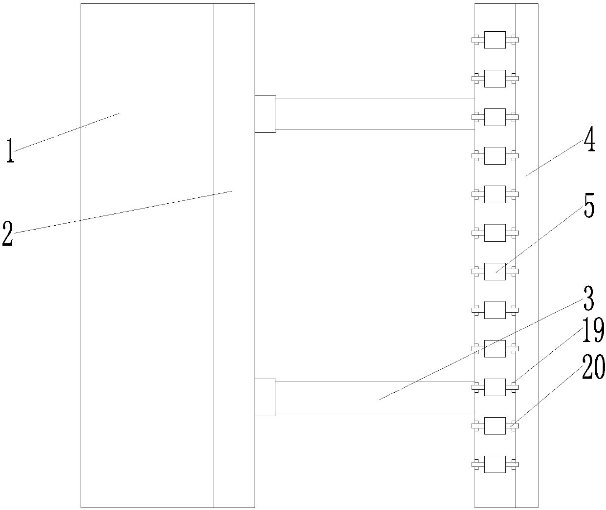
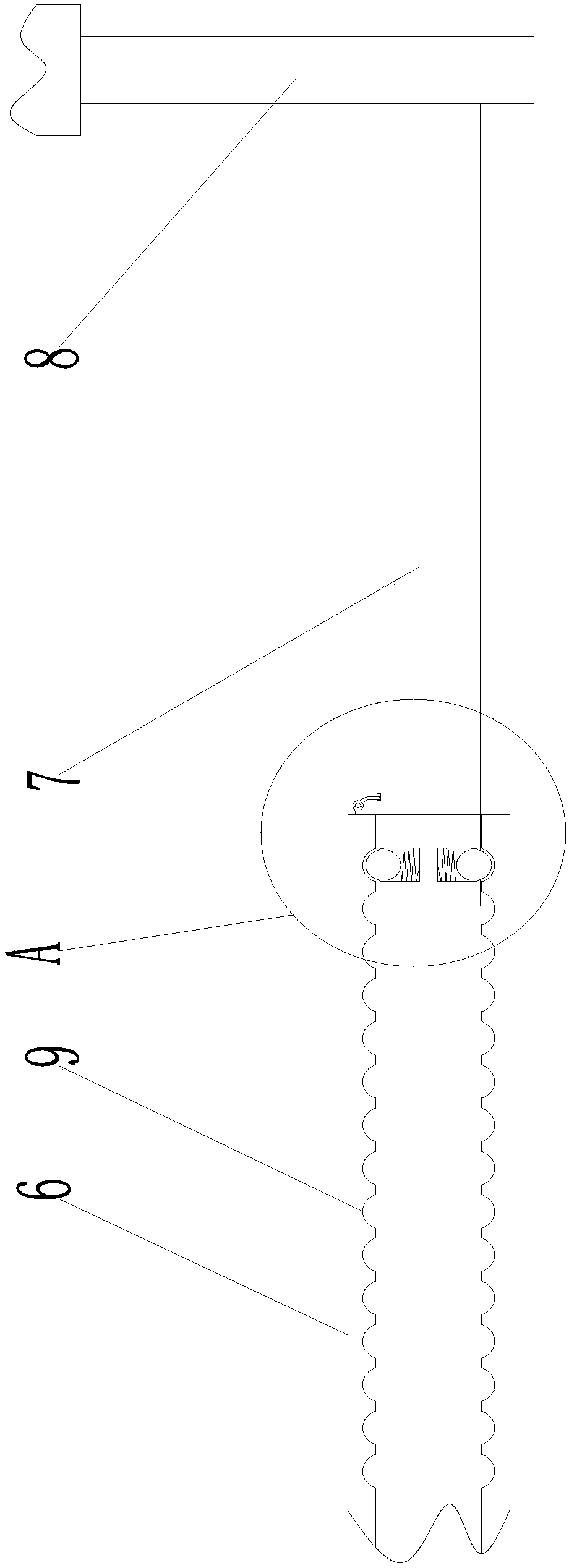
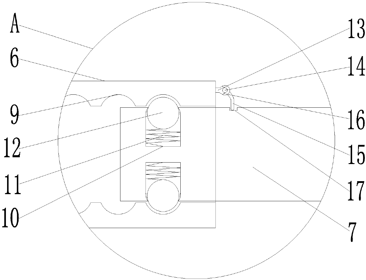
[0018] Such as figure 1 The conveying mechanism shown that can be applied to plates of different widths includes a support 1, a conveyor belt 2, several such as figure 2 In the shown telescopic mechanism 3 and auxiliary guide rail 4, the conveyor belt is arranged in the middle of one side of the support, and several telescopic mechanisms are fixed on the lower part of one side of the frame, and the auxiliary guide rail is arranged on the outside of the frame through several telescopic mechanisms. The belt is arranged in parallel, and several rollers 5 are installed on the auxiliary guide rail; the telescopic mechanism includes a sleeve 6, a telescopic rod 7 and a fixed rod 8, the sleeve is fixed on the lower part of the frame and one end extends into the frame, and the inner wall of the sleeve is s...


PUM


Abstract

The invention relates to the technical field of plate conveying equipment and particularly discloses a conveying mechanism suitable for plates with different widths. The conveying mechanism comprisesa bracket, a conveyer belt, a plurality of telescopic mechanisms and an auxiliary guide rail, wherein the auxiliary guide rail is arranged at the external part of a rack through the telescopic mechanisms; a plurality of idler wheels are arranged on the auxiliary guide rail; each of the telescopic mechanisms comprises a sleeve, a telescopic rod and a fixed rod; a plurality of circular arc-shaped limiting grooves are formed in the inner walls of the sleeve side by side; a plurality of guide grooves are formed in the end, close to the sleeve, of the telescopic rod; springs are arranged at the bottoms of the guide grooves; positioning balls are arranged at the free ends of the springs; a shrinking structure is arranged at the opening of each of the guide grooves; the diameter at the opening ofeach of the guide grooves is smaller than the external diameter of the corresponding positioning ball; the positioning ball protrudes out of the guide groove; the end, far away from the correspondingguide groove, of the telescopic rod is fixedly connected with the corresponding fixed rod; and the upper ends of the fixed rods are fixed at the bottom of the auxiliary guide rail. The conveying mechanism has the characteristics of being adjustable in width, higher in adaptation and higher in conveying efficiency.

Description

technical field [0001] The invention relates to the technical field of plate conveying equipment, in particular to a conveying mechanism applicable to plates of different widths. Background technique [0002] At present, in the home furnishing industry, after the sawing of the board is completed, for subsequent use, an edge banding machine is usually used to seal the sawn board. The current edge banding process is highly mechanized. In order to improve the edge banding Efficiency requires the use of conveying equipment to continuously send the boards that need to be edge-banded to the edge-banding machine. The existing conveying equipment that sends the boards to the edge-banding machine usually simply uses a motor to drive the gear to drive the conveyor belt to rotate. The plate is rotated to be sent to the edge banding machine for edge banding. No matter what width the plate is, the same conveying equipment is used uniformly, which has poor adaptability. When it is necessa...

Claims


Application Information

Patent Timeline
Patent Type & Authority Applications(China)
IPC IPC(8): B65G35/00B65G15/22B65G13/00
Inventor 唐远明张江费建良蔡伟于克徐东辉
Owner 浙江云峰莫干山家居用品有限公司
Why Eureka
Try Eureka