Unwinding and winding device and use method thereof

A technology for rewinding and unwinding rolls and rolls, which is applied in the field of automation equipment and can solve problems such as uneven upper ends of veneer rolls and unstable placement

Inactive Publication Date: 2018-01-19
德清德沃装饰材料有限公司
View PDF7 Cites 2 Cited by
  • Summary
  • Abstract
  • Description
  • Claims
  • Application Information

AI Technical Summary

Problems solved by technology

The thickness of the veneer is generally less than 0.5mm, and the length of the veneer wound in a roll of veneer is very long, so it is very easy to have the problem of une

Method used


Image

  • Unwinding and winding device and use method thereof
  • Unwinding and winding device and use method thereof

Examples


Embodiment 1

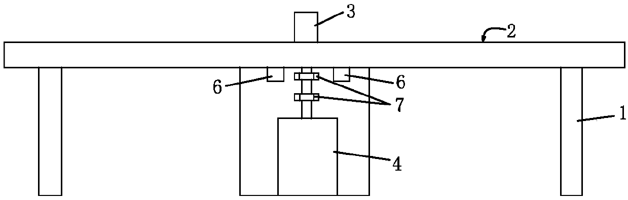
[0016] Such as figure 1 A retractable winding device shown includes a winding platform 2 installed on a bracket 1, the table surface of the winding platform 2 is a smooth plane, and an inflatable shaft 3 is installed on the winding platform, and the inflatable shaft 3 The lower end is connected by the drive shaft of the drive motor 4 through the transmission device, and the inflatable shaft 3 is driven by the drive motor 4 to rotate forward or reversely according to its functional requirements. In order to ensure that the inflatable shaft can rotate smoothly. Bearings are arranged on the drive shaft of the expansion shaft or the drive motor or the connecting shaft connecting the air expansion shaft and the drive shaft of the drive motor, and are connected to the support 1 by the bearing seat 7 . The unwinding device also includes an air-expanding head used in conjunction with the air-expanding shaft 3, and a shelf for placing the air-expanding head is provided on the support 1...

Embodiment 2

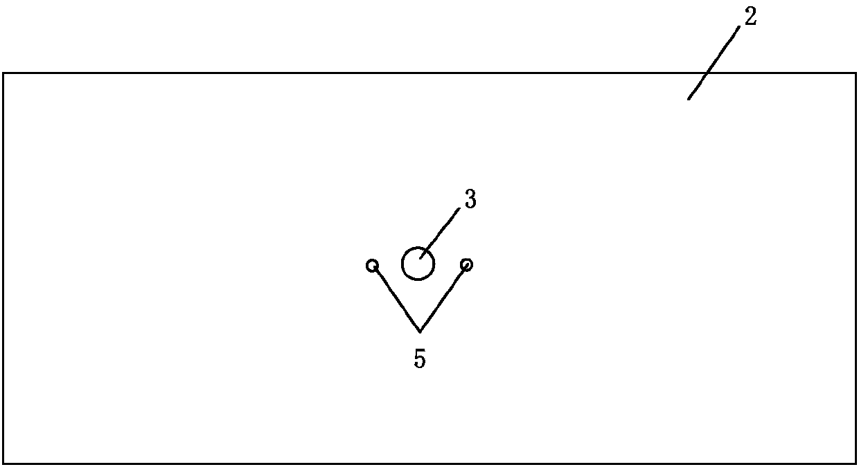
[0023] The difference between this embodiment and Embodiment 1 is that the winding platform is provided with at least two jacking blocks 5 arranged symmetrically along the inflation axis, and the jacking blocks 5 are arranged in the winding area of ​​the veneer roll to lift The block 5 can be lifted and installed on the winding platform 2, and the lower end of the jack-up block 5 is connected with the telescopic rod of the driving cylinder 6. When the telescopic rod of the driving cylinder 6 is in the retracted state, the upper end surface of the jacking block 5 is lower than or flush with the table surface of the winding platform 2 . After the telescoping rod of driving cylinder 6 stretches out, the jacking block is jacked up, so that the upper end of the jacking block 5 stretches out a distance above the table top of the winding platform.

[0024] After the veneer roll is completed through the inflatable shaft 3 and the pressure plate, it may be difficult to take out the ven...


PUM


Abstract

The invention discloses an unwinding and winding device and a use method thereof. The unwinding and winding device comprises a winding platform mounted on a support. A gas-expansion shaft is rotationally mounted on the winding platform. The lower end of the gas-expansion shaft is connected with a driving shaft of a driving motor through a transmission device. In a deflated state, the diameter of the gas-expansion shaft is smaller than the diameter of a reel which is used for winding veneers, and after being inflated, the gas-expansion shaft can clamp the reel from the inner side and drive thereel and a winding shaft to rotate synchronously. The winding platform is provided with at least two ejecting blocks symmetrically arranged along the gas-expansion shaft, the ejecting blocks are arranged on the winding platform in a lifting mode, and the lower ends of the ejecting blocks are connected with telescopic rods of driving cylinders. The winding process in the last production stage of veneers is achieved through cooperation of a pressing plate and the gas-expansion shaft, so that obtained veneer rolls are orderly in end face; and moreover, wound veneer rolls can be scattered and thentidied again.

Description

technical field [0001] The invention relates to the field of automation equipment, in particular to a retractable winding device and a use method thereof. Background technique [0002] Wood veneer is a decorative material used for direct cladding of cabinets, furniture, wooden doors, etc., and is generally used for edge banding and decoration. The thickness of the veneer is generally less than 0.5mm, and the length of the veneer wound in a roll of veneer is very long, so it is very easy to have the problem of uneven upper ends of the veneer roll after the production is completed, resulting in multiple stacks of veneer rolls There may be problems with unstable placement when stacked. In particular, the part near the outside of a roll of veneer is more likely to have uneven upper ends. Contents of the invention [0003] In order to solve the above problems, the object of the present invention is to provide a winding device for winding veneer, which can also unwind the roll...

Claims


Application Information

Patent Timeline
IPC IPC(8): B65H18/02B65H18/10B65H75/24
Inventor 陆琪丰
Owner 德清德沃装饰材料有限公司
Why Eureka
Try Eureka