
Crane box end anti-sway device

A technology of anti-rolling device and crane, which is applied in the direction of transportation and packaging, load hanging components, etc. It can solve the problems of reduced site utilization, hidden safety hazards, and difficulties in container stacking, and achieve the effect of promoting stability and slowing down swings

Active Publication Date: 2019-07-05
SHANGHAI VEHICLE LOADING EQUIP CO LTD
View PDF5 Cites 0 Cited by
  • Summary
  • Abstract
  • Description
  • Claims
  • Application Information

AI Technical Summary

Problems solved by technology

[0002] Cranes are one of the commonly used handling tools in freight warehouses and docks. They are mainly used for loading, unloading, handling and stacking of containers; common cranes include cart running mechanism, trolley running mechanism, supporting legs, lifting mechanism and cab; the driver The container is grasped by operating the grasping mechanism at the lower part of the trolley running mechanism, and the handling and stacking of the container is realized through the cooperative transfer of the cart and trolley running mechanism; during the transfer process, the container will swing, and at the same time, because the container is suspended on the trolley running There is a large swing arm in the lower part of the mechanism. Therefore, a small disturbance will generate a large swing force and swing range for the container, which will cause great difficulties for the stacking of the container; when the container lands, the box body is swaying , it is difficult to arrange the upper and lower boxes facing each other; when the containers are not stacked neatly, the stability of the container stack will be greatly reduced, easy to dump, and there will be a greater safety hazard. At the same time, the utilization rate of the site will be reduced, which is not conducive to Item management, search and verification

Method used


Image

  • Crane box end anti-sway device
  • Crane box end anti-sway device
  • Crane box end anti-sway device

Examples


Embodiment

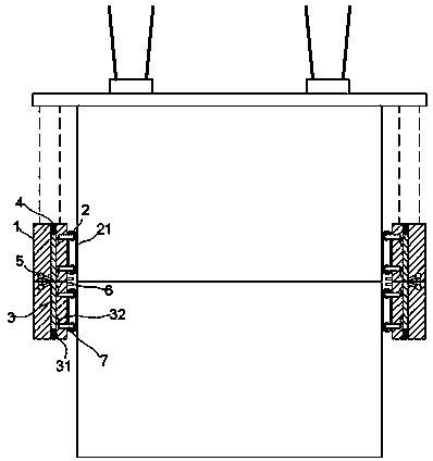
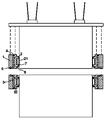
[0019] exist figure 1 , figure 2 In the shown embodiment, the anti-sway device at the end of the crane box includes a housing 1 made of permanent magnetic material, and the magnetic pole connection line of the permanent magnetic material is parallel to the front and rear connection lines of the housing 1;

[0020] A group of driving rollers 2 are installed on the bottom of the housing 1, and the driving rollers 2 can freely rotate around their own shafts; between the driving rollers 2, a driving crawler 21 is set, and the driving crawler 21 is composed of permanent magnets. joined together;

[0021] An adjustment slot is provided inside the housing 1, and an adjustment column 3 is slidably arranged in the adjustment slot, and one end of the adjustment column 3 is connected with the rear part of the housing 1 through a tension spring 31; An electronically controlled telescopic rod 4 is installed between the rear end of 3 and the housing 1, and the electrically controlled tel...


PUM


Abstract

The invention relates to an anti-shaking device for a crane box end. The anti-shaking device comprises a shell, wherein the shell is made of permanent magnet material; a set of driving rollers are arranged at the bottom part of the shell, and the driving rollers can freely rotate around the rotating axes of the driving rollers; a driving crawler belt is arranged between the driving rollers in a sleeving mode, and the driving crawler belt is formed by splicing permanent magnet pieces in an end-to-end mode; an adjusting groove is formed in the shell, an adjusting column is arranged in the adjusting groove in a sliding mode, one end of the adjusting column is connected with the rear part of the shell through a tension spring, and the other end of the adjusting column can slide out of the front part of the shell along the adjusting groove; a pressure-sensitive limiter is further arranged at the front part of the shell; adjusting rods are arranged on the rotating axes, and the end parts ofthe adjusting rods extend into the shell; and limiting pieces matched with the adjusting rods are arranged on the adjusting column. According to the anti-shaking device, swing amplitude of a containercan be effectively reduced, stacking accuracy and uniformity are improved, so that stability of a box pile is improved, and the utilization rate of the field is improved.

Description

technical field [0001] The invention relates to a crane accessory, in particular to an anti-sway device. Background technique [0002] Cranes are one of the commonly used handling tools in freight warehouses and docks. They are mainly used for loading, unloading, handling and stacking of containers; common cranes include cart running mechanism, trolley running mechanism, supporting legs, lifting mechanism and cab; the driver The container is grasped by operating the grasping mechanism at the lower part of the trolley running mechanism, and the handling and stacking of the container is realized through the cooperative transfer of the cart and trolley running mechanism; during the transfer process, the container will swing, and at the same time, because the container is suspended on the trolley running There is a large swing arm in the lower part of the mechanism. Therefore, a small disturbance will generate a large swing force and swing range for the container, which will cau...

Claims


Application Information

Patent Timeline
Patent Type & Authority Patents(China)
IPC IPC(8): B66C13/06B66C13/08
Inventor 丁向峰
Owner SHANGHAI VEHICLE LOADING EQUIP CO LTD
Learn More