Bio-fertilizer fermentation device

A fermentation device and biological fertilizer technology, applied in the field of fermentation tanks, can solve the problems of difficult automatic production, complicated operation, time-consuming and labor-intensive, etc., and achieve the effects of avoiding long-distance transportation, good effect and improving efficiency.

Inactive Publication Date: 2018-01-19
董华江
View PDF8 Cites 2 Cited by
  • Summary
  • Abstract
  • Description
  • Claims
  • Application Information

AI Technical Summary

Problems solved by technology

In the existing production process, the cultivation of strains is often set up in multiple locations, and the mixing needs to be transported over a long distance, which is very time-consuming and labor-intensive, and it is not easy to realize automated production
[0003] For example, the existing bio-organic fertilizers, in addition to the organic matter itself, also include nitrogen-fixing bacteria, actinomycetes, silicate bacteria, Bacillus aspartate, Paenibacillus polymyxa, yeast, etc., the cultivation environment of each strain Different, it must be cultivated separately, and materials need to be transported from multiple culture tanks when mixing, the operation is very complicated and cumbersome
At the same time, the organic fertilizer itself also needs to be fermented before being reused. It is very time-consuming and labor-intensive to mix a large amount of organic fertilizer and bacteria to form organic fertilizer.

Method used


Image

  • Bio-fertilizer fermentation device
  • Bio-fertilizer fermentation device
  • Bio-fertilizer fermentation device

Examples


Embodiment Construction

[0039]The present invention will be further described in detail below in conjunction with the accompanying drawings, so that those skilled in the art can implement it with reference to the description.

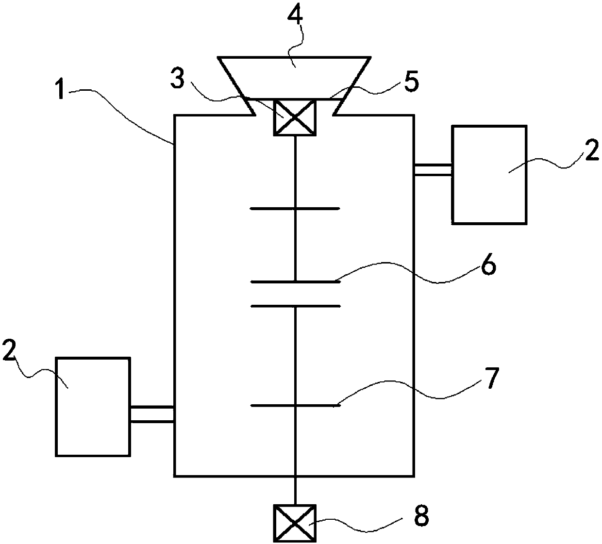
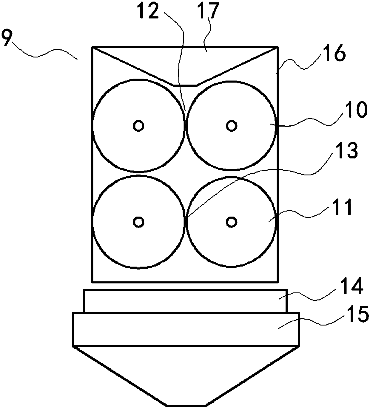
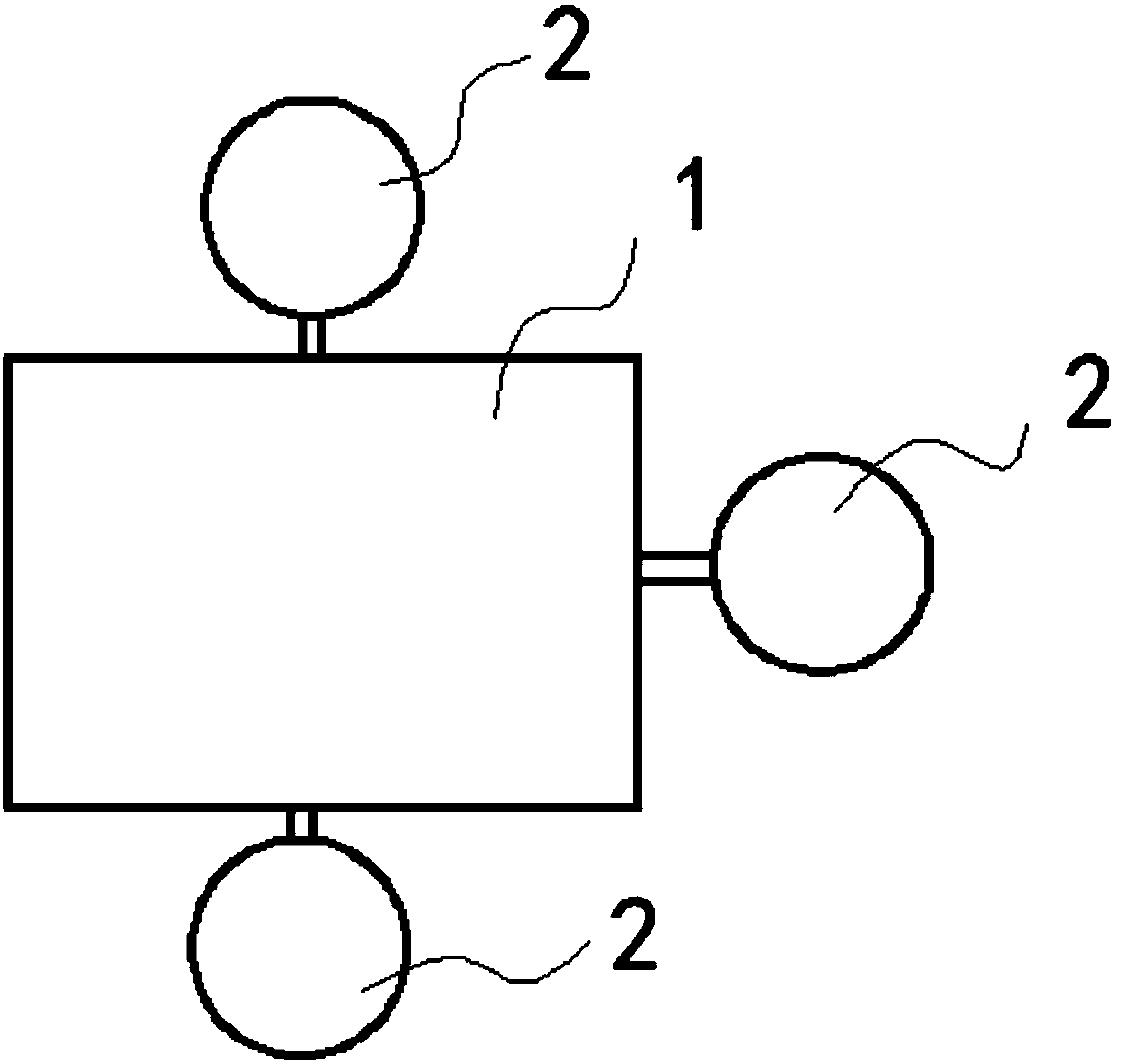
[0040] Such as figure 1 , 2 Shown in and 3, a kind of biological fertilizer fermentation device, wherein, comprises:

[0041] The main tank body 1 has a rectangular cross-section and has a cavity inside. The top of the main tank body 1 is provided with an upper opening, and the upper opening is matched with a funnel 4, and the lower part of the funnel is engaged with the opening. , the upper part extends upwards and outwards to form an open feed inlet, and a flat plate 5 is horizontally arranged on the upper opening of the main tank body 1, and the flat plate 5 is connected and fixed to the main tank body by at least three fixing bars, and the There is a gap for materials to pass between the flat plate 5 and the upper opening, and the bottom of the main tank body 1 is closed...


PUM


Abstract

The invention discloses a bio-fertilizer fermentation device, which comprises a main tank body, a first stirring pump, a second stirring pump, at least three sub tank bodies and a heating unit, wherein the main tank body is of a rectangular structure; an upper opening is formed in the top of the main tank body; the upper opening is provided with a flat plate; the flat plate is fixed with the maintank body through a fixing strip; a gap is formed between the flat plate and the upper opening; the bottom of the main tank body is provided with a discharging opening; the first stirring pump is arranged at the bottom surface of the flat plate; a rotating shaft of the first stirring pump downwards extends; a first stirring blade is arranged on the rotating shaft of the first stirring pump; the first stirring blade is of a spiral structure; the second stirring pump is arranged at the bottom of the main tank body; the rotating shaft of the second stirring pump extends into the main tank body from the bottom of the main tank body; a second stirring blade is arranged on the rotating shaft of the second stirring pump; the second stirring blade is of a spiral structure and has the opposite rotating direction to the first stirring blade; the distance between the first stirring blade and the second stirring blade is 20 to 30cm; the sub tank bodies are distributed outside the main tank body; the sub tank body is provided with a guide pipe communicating to a cavity from the upper part or the lower part of the main tank body; the heating unit is arranged at the bottom of the main tank body.

Description

technical field [0001] The invention relates to the technical field of fermentation tanks, and more specifically, the invention relates to a biological fertilizer fermentation device. Background technique [0002] Biological fertilizers often contain multiple bacterial strains, which are cultivated independently, and then mixed to obtain biological fertilizers. In the existing production process, the cultivation of strains is often set up in multiple locations, and the mixing needs to be transported over a long distance, which is very time-consuming and labor-intensive, and it is not easy to realize automated production. [0003] For example, the existing bio-organic fertilizers, in addition to the organic matter itself, also include nitrogen-fixing bacteria, actinomycetes, silicate bacteria, Bacillus aspartate, Paenibacillus polymyxa, yeast, etc., the cultivation environment of each strain Different, it must be cultivated separately, and materials need to be transported fr...

Claims


Application Information

Patent Timeline
Patent Type & Authority Applications(China)
IPC IPC(8): C05F17/02
CPCY02W30/40
Inventor 卢志文
Owner 董华江
Why Eureka
Try Eureka