Supercharge Your Innovation With Domain-Expert AI Agents!

Parallel-shaft transmission assembly with selectable electrification

A technology of transmission and assembly, applied in the field of motor vehicle parallel shaft transmission assembly

Inactive Publication Date: 2018-01-19
GM GLOBAL TECH OPERATIONS LLC
View PDF6 Cites 1 Cited by
  • Summary
  • Abstract
  • Description
  • Claims
  • Application Information

AI Technical Summary

Problems solved by technology

However, while all forward gears are always in mesh with each other, there is often backlash between the reverse gears

Method used


Image

  • Parallel-shaft transmission assembly with selectable electrification
  • Parallel-shaft transmission assembly with selectable electrification
  • Parallel-shaft transmission assembly with selectable electrification

Examples


Embodiment Construction

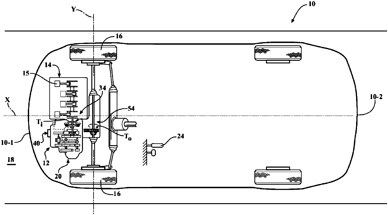
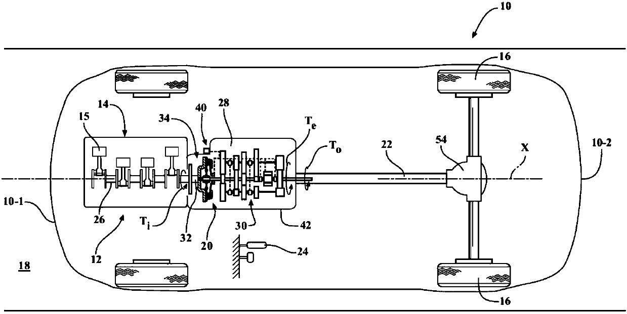
[0026] refer to figure 1 and figure 2 , depicts a vehicle 10 having a powertrain 12 . Vehicle 10 may include, but is not limited to, commercial vehicles, industrial vehicles, passenger cars, airplanes, boats, trains, and the like. It is also contemplated that vehicle 10 may be any mobile platform, such as an aircraft, all-terrain vehicle (ATV), boat, personal mobility device, robot, etc., for the purposes of the present invention.

[0027] Powertrain 12 includes a power source 14 configured to generate torque T relative to a road surface 18 through driven wheels 16 i , for the propulsion of the vehicle 10 . The powertrain 12 also includes a transmission assembly 20 operatively connected to the power source 14, i.e. externally mounted to the power source and configured to transmit the torque T produced by the power source i Passed to the driven wheel 16. The transmission assembly 20 is further configured to receive and then increase or decrease torque T i , to obtain the...


PUM


Abstract

A transmission assembly for mounting to an external power-source includes an input shaft configured to receive power-source torque. The transmission assembly also includes an output member configuredto transmit a transmission output torque to drive a load. The transmission assembly additionally includes a countershaft driven by and arranged parallel to the input shaft. The countershaft has a first gear-set rotatably mounted thereon and is configured to drive the output member. The transmission assembly also includes a second gear-set in mesh with the first gear-set and operatively connected to the output member. Furthermore, the transmission assembly includes an electric motor configured to be selectively connected to the input shaft via a first torque transfer device and to the output member via a second torque transfer device to thereby provide a variable electric motor internal torque input to the transmission assembly. A vehicle having such a transmission and power-source is alsodisclosed.

Description

technical field [0001] The present invention relates to an automotive parallel shaft transmission assembly having selectable connections for an internal electric motor. Background technique [0002] A typical manual transmission for a motor vehicle has several parallel shafts with various gears and other components connected thereto. Typically, rear-wheel drive manual transmissions have three shafts: an input or drive shaft that transmits input torque to the transmission, a layshaft or countershaft, and a driven or output shaft that transmits torque out of the transmission. The countershaft is an intermediate shaft mounted within the transmission assembly parallel to the input and output shafts, and carries a series of transmission gears of different sizes. The countershaft gears are rotated by the rotation of the input shaft, but do not transmit the initial drive of the transmission to or from the transmission. Typically, the countershaft gear can either turn freely on a ...

Claims


Application Information

Patent Timeline
IPC IPC(8): F16H3/20F16H57/023F16H61/26F16H63/30
CPCB60K6/387B60K6/48B60K6/547F16H3/093B60K2006/4808B60K2006/4825B60K2006/4841F16H2003/0931F16H2200/0056B60Y2200/90F16H3/006Y02T10/62B60K6/36B60K6/445B60Y2300/73B60Y2300/80F16H3/091F16H37/0806
Inventor D·L·罗宾耐特T·辛格
Owner GM GLOBAL TECH OPERATIONS LLC
Features
  • R&D
  • Intellectual Property
  • Life Sciences
  • Materials
  • Tech Scout
  • Unparalleled Data Quality
  • Higher Quality Content
  • 60% Fewer Hallucinations
Learn More