Supercharge Your Innovation With Domain-Expert AI Agents!

Infusion pipeline framework structure device in valve body

A technology for infusion tubes and valve bodies, applied in the field of infusion tubes, which can solve the problems of resource consumption of metal materials, short service life, inconvenient disassembly and assembly, and achieve the effects of saving metal materials, long service life and simple structure

Active Publication Date: 2018-01-19
刘道灵
View PDF5 Cites 0 Cited by
  • Summary
  • Abstract
  • Description
  • Claims
  • Application Information

AI Technical Summary

Problems solved by technology

[0009] Faucets or valves are essential control components for plastic pipes that convey fluids. With the continuous improvement of people's living standards, people are increasingly demanding the quality of living water, the appearance of faucets and valves, and their practicability. Traditional cast iron painted faucet valves are improved to cast copper chrome-plated faucet valves. However, with the increasing shortage of metal resources on the earth, and cannot continue to regenerate, because the existing faucets have a metal integral structure inside, when the faucet's interior When the infusion pipeline is damaged, the entire faucet must be replaced. Generally, the price of the faucet is relatively high, and it is inconvenient to disassemble and assemble. If it is damaged, it will be replaced, which will cause economic waste, short service life, and indirectly consume metal material resources. Therefore, a faucet is urgently needed. A new structure of the faucet to change the status quo

Method used


Image

  • Infusion pipeline framework structure device in valve body
  • Infusion pipeline framework structure device in valve body
  • Infusion pipeline framework structure device in valve body

Examples


Embodiment Construction

[0026] The following will clearly and completely describe the technical solutions in the embodiments of the present invention with reference to the accompanying drawings in the embodiments of the present invention. Obviously, the described embodiments are only some, not all, embodiments of the present invention.

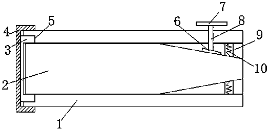
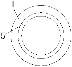
[0027] refer to Figure 1-3 , an infusion pipeline frame structure device in a valve body, comprising a valve body 1, the valve body 1 is a cylindrical structure, an external thread is provided at one end of the outer wall of the valve body 1, the inside of the valve body 1 is a hollow structure, the valve body 1 One end of the outer wall is inwardly provided with an annular groove 5, and the diameter of the annular groove 5 is smaller than the outer diameter of the valve body 1, and one end of the valve body 1 is threadedly connected with a locking cover 4, and the circumferential inner wall of the locking cover 4 is provided with an internal thread, and The inner t...


PUM


Abstract

The invention discloses an infusion pipeline framework structure device in a valve body. The device comprises a valve body, the valve body is of a cylindrical structure, outer threads are formed in one end of the circumference outer wall of the valve body, and the interior of the valve body is of a hollow structure; an annular groove is inwards formed in the outer wall of one end of the valve body, and the diameter of the annular groove is smaller than the outer diameter of the valve body; the end with the outer threads of the valve body is in threaded connection with a locking cover, inner threads are formed in the inner wall of the circumference of the locking cover, and the inner threads and the outer thread are matched; and a clamping ring is welded to the outer wall of the side, closeto the valve body, of the locking cover, and the diameter of the clamping ring is matched with the diameter of the annular groove. The device is simple in structure, when an infusion tube is damagedand can be used, the locking cover is unscrewed and separated from the valve body, a pull rod and a connecting block are separated, the infusion tube is directly taken out and replaced and maintained,the whole process is convenient and rapid, the whole faucet does not need to be replaced, economic waste is avoided, the metal materials are saved, and the service life is long.

Description

technical field [0001] The invention belongs to the technical field of transfusion tubes in a valve body, and in particular relates to a frame structure device of a transfusion pipeline in a valve body. Background technique [0002] Compared with traditional cast iron pipes, galvanized steel pipes, cement pipes and other pipes, plastic pipes have the advantages of energy saving, environmental protection, light weight and high strength, corrosion resistance, smooth inner wall without scaling, easy construction and maintenance, and long service life. Widely used in building water supply and drainage, urban and rural water supply and drainage, city gas, electric power and optical cable sheathing, industrial fluid transportation, agricultural irrigation and other construction, municipal, industrial and agricultural fields. [0003] In recent years, my country's macro-economy has continued to accelerate, and the demand for plastic pipes in construction engineering, municipal engi...

Claims


Application Information

Patent Timeline
Patent Type & Authority Applications(China)
IPC IPC(8): F16K7/06F16K27/00
Inventor 刘道灵
Owner 刘道灵
Features
  • R&D
  • Intellectual Property
  • Life Sciences
  • Materials
  • Tech Scout
  • Unparalleled Data Quality
  • Higher Quality Content
  • 60% Fewer Hallucinations
Learn More