A valve device for increasing the opening and closing speed of the coating transition chamber

A technology of valve device and door opening and closing, which is applied in the direction of valve device, valve operation/release device, valve details, etc. It can solve the problems that the cylinder cannot reach the detection switch position, the cylinder pulls up and down slowly, and the waiting time of the glass is prolonged slowly. , to achieve the effects of shortening the intake time, improving the exhaust efficiency, and improving the sputtering film efficiency

Active Publication Date: 2019-05-31
XIANNING CSG ENERGY SAVING GLASS
View PDF10 Cites 0 Cited by
  • Summary
  • Abstract
  • Description
  • Claims
  • Application Information

AI Technical Summary

Problems solved by technology

[0004] 1) The cylinder pulls up and down slowly, and the glass waits for a long time in the process of entering the vacuum step by step and leaving the vacuum chamber
[0005] 2) When the glass enters from the first level of vacuum state to the next level of vacuum state, it is necessary to wait for the door between the vacuum buffer chambers to be completely closed before proceeding to the next step. The slow movement of the cylinder prolongs the waiting time for the glass
[0006] 3) The slow pulling of the cylinder sometimes causes the cylinder to fail to reach the position of the detection switch, resulting in failure

Method used


Image

  • A valve device for increasing the opening and closing speed of the coating transition chamber
  • A valve device for increasing the opening and closing speed of the coating transition chamber
  • A valve device for increasing the opening and closing speed of the coating transition chamber

Examples


Embodiment 1

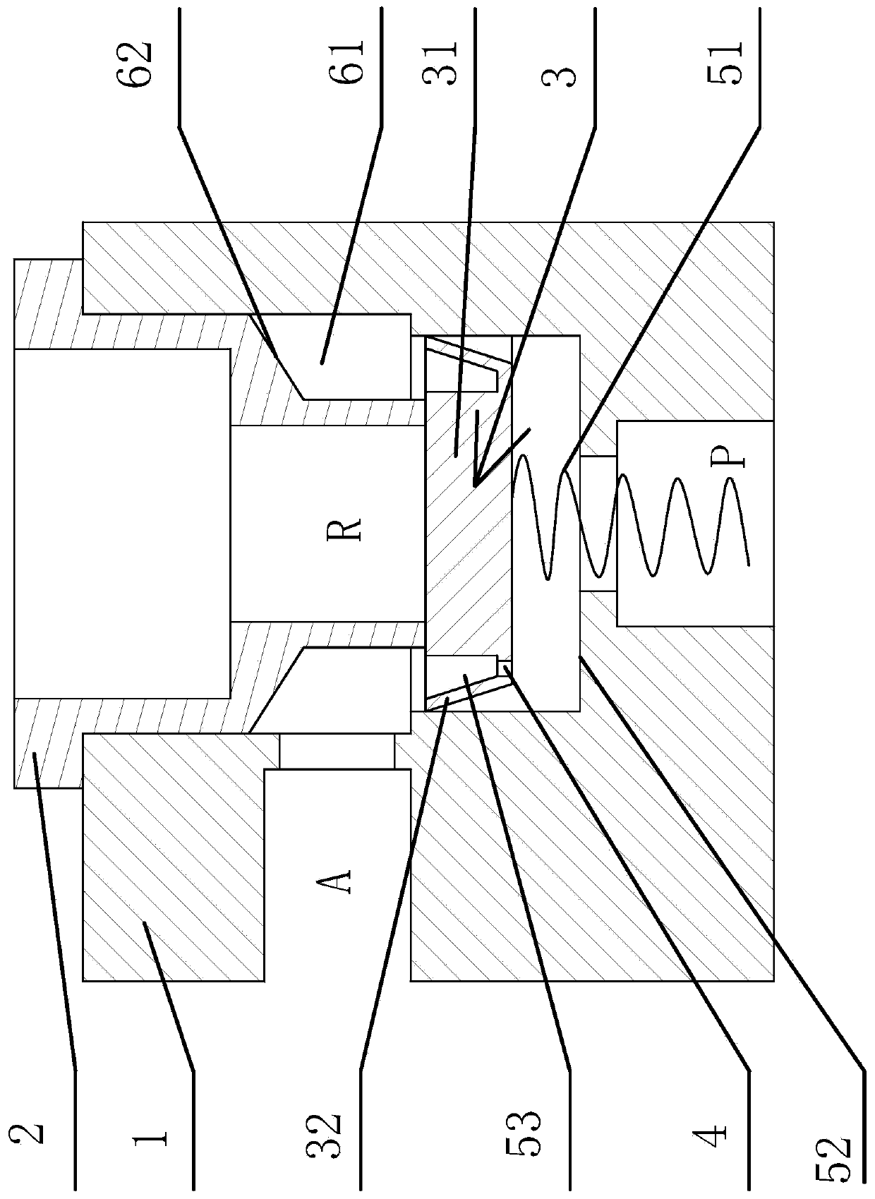
[0041] Such as figure 1 As shown, the valve device includes a main valve body 1, an auxiliary valve body 2 connected to the main valve body 1, and a cup piston 3 located between the main valve body 1 and the auxiliary valve body 2. The main valve body 1 has an air inlet port P and working port A, the auxiliary valve body 2 has an exhaust port R, and the cup piston 3 is provided with a main air intake hole 4 through the working port A and the air inlet P, and one side of the cup piston 3 is connected to the main There is a pre-tension spring 51 connected between the valve body 1, the other side of the cup piston 3 can cover the exhaust port R on the auxiliary valve body 2, the main valve body 1 has a stepped surface 52, and the cup piston 3 When moving down, the stepped surface 52 can cover the main air intake hole 4 on the cup piston 3 and connect the working port A with the exhaust port R.

[0042] Air intake: the air flow enters the working port A through the air inlet P an...

Embodiment 2

[0049] The content of this embodiment is basically the same as that of Embodiment 1, the difference is:

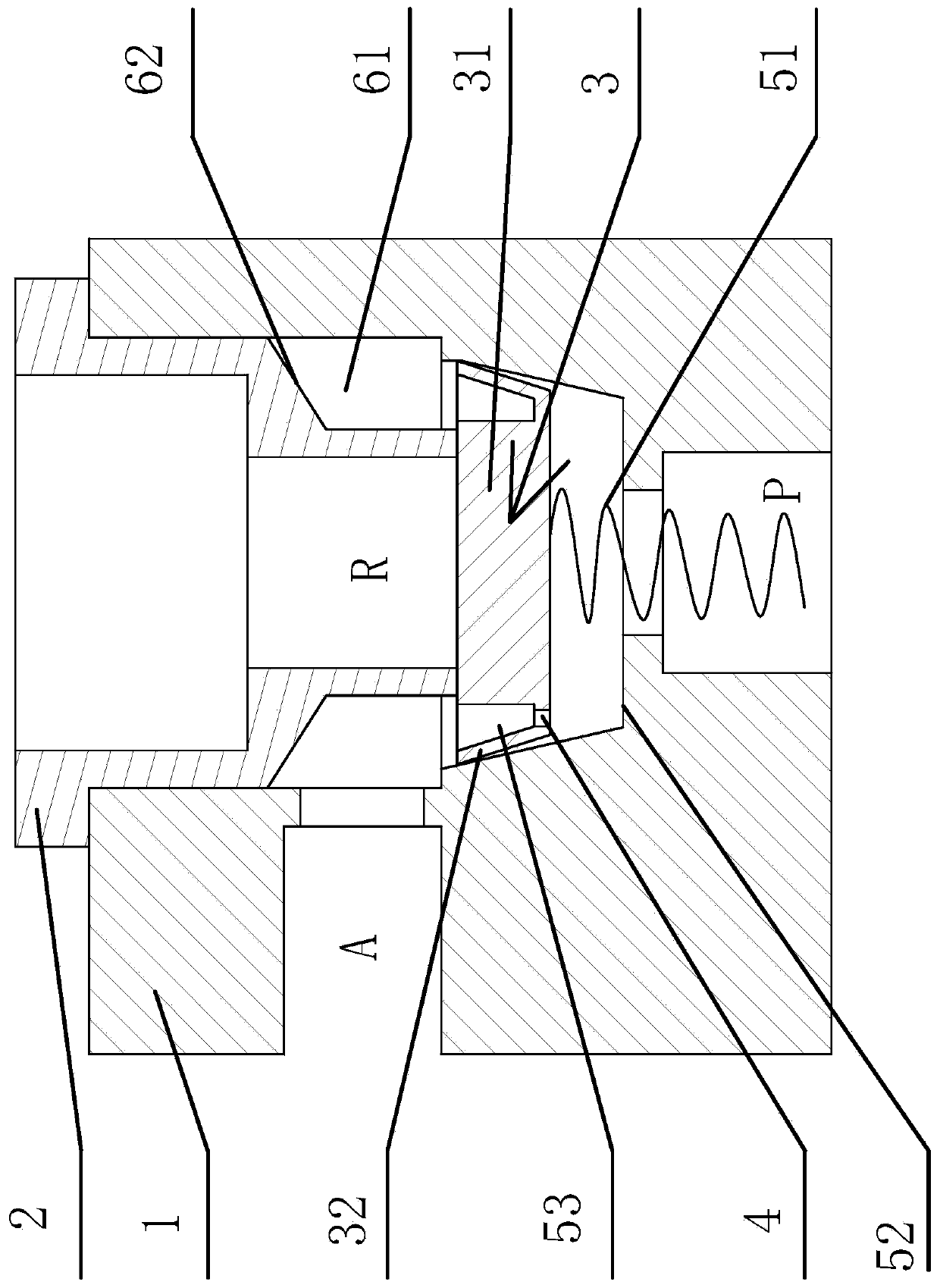
[0050] Such as image 3 As shown, the outer surface of the soft sealing ring 32 is a slope corresponding to the weakening groove 53, and the wall surface on the main valve body 1 that is sealed with the cup piston 3 is adapted to the outer surface of the soft sealing ring 32; 3 moves down, and when exhausting, the soft sealing ring 32 can be squeezed, thereby reducing the flow area of ​​the main air intake hole 4, increasing the sealing strength between the cup piston 3 and the main valve body 1, and making the exhaust more efficient. Smooth, exhaust reaction time is shortened.

Embodiment 3

[0052] The content of this embodiment is basically the same as that of Embodiment 1, the difference is:

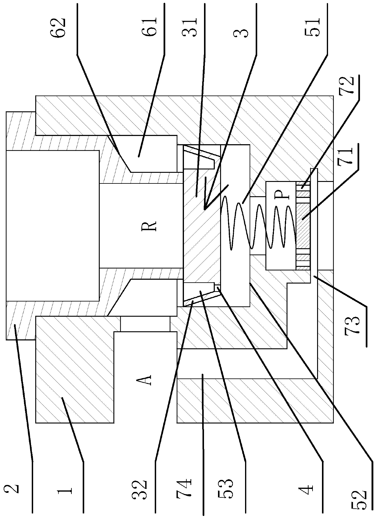
[0053] Such as figure 2 As shown, the air inlet P is provided with a valve block 71 that can move up and down along the peripheral wall of the air inlet P. The valve block 71 is provided with a through hole 72, and the two ends of the pre-tension spring 51 are respectively connected to the valve block 71 and the cup piston. 3. The main valve body 1 is provided with an annular air groove 73 that can communicate with the air inlet P, and an auxiliary air inlet 74 located in the main valve body 1 is provided between the air groove 73 and the working port A; the valve block 71 can Cover the air groove 73; when the intake air is being carried out, the valve block 71 can move up under the action of the intake air pressure, so that the intake port P and the working port A are connected, and the intake air can be quickly inhaled when the intake air pressure is high , shorten the...


PUM


Abstract

The invention provides a valve device for improving the door opening and closing speed of a coating transition chamber, and belongs to the technical field of coating glass production. The valve devicesolves the technical problems of low coating efficiency of existing coating equipment and the like. The valve device for improving the door opening and closing speed of the coating transition chambercomprises a main valve body, an auxiliary valve body connected with the main valve body and a packing leather piston located between the main valve body and the auxiliary valve body, the main valve body is provided with an air inlet and a working opening, the auxiliary valve body is provided with an exhaust opening, and the packing leather piston is provided with a main air inlet hole penetratingthe working opening and the air inlet; and a pre-tightening spring is arranged between one side face of the packing leather piston and the main valve body, the exhaust opening in the auxiliary valvebody can be shielded by the other side face of the packing leather piston, the main valve body is provided with a step face, and the step face can shield the packing leather piston when the packing leather piston moves downwards to communicate the working opening and the exhaust opening. The valve device has the beneficial effects of being efficient in air inlet and exhaust, simple and reliable instructure and the like.

Description

technical field [0001] The invention belongs to the technical field of coated glass production, and relates to a valve device for increasing the speed of opening and closing doors of a coating transition chamber. Background technique [0002] Magnetron sputtering coating technology is one of the most important technologies in industrial coating production at present. Magnetron sputtering has the advantages of high speed, low temperature, low damage, etc., fast deposition rate, small temperature change of the substrate, and little damage to the film layer And so on a series of advantages. Widely used in the large-area architectural glass coating industry. With the continuous maturity of industry processing technology and the gradual deepening of market competition, cost reduction has become a trend. Due to the use of high-power power-consuming equipment, water and electricity bills are always a major production cost. This is especially true for the use of equipment for glass...

Claims


Application Information

Patent Timeline
Patent Type & Authority Patents(China)
IPC IPC(8): F16K11/044F16K31/383
Inventor 江亮
Owner XIANNING CSG ENERGY SAVING GLASS
Why Eureka
Try Eureka