Electromechanical equipment mounting stand

A technology for installing machine bases and electromechanical equipment, which is applied in the direction of mechanical equipment, supporting machines, machine tables/supports, etc., and can solve other problems such as insufficient functions

Inactive Publication Date: 2018-01-19
ZHENJIANG QILONG TECH CO LTD
View PDF6 Cites 2 Cited by
  • Summary
  • Abstract
  • Description
  • Claims
  • Application Information

AI Technical Summary

Problems solved by technology

[0004] Although the above-mentioned patent solves the difficulty of movi

Method used


Image

  • Electromechanical equipment mounting stand
  • Electromechanical equipment mounting stand

Examples


specific Embodiment approach

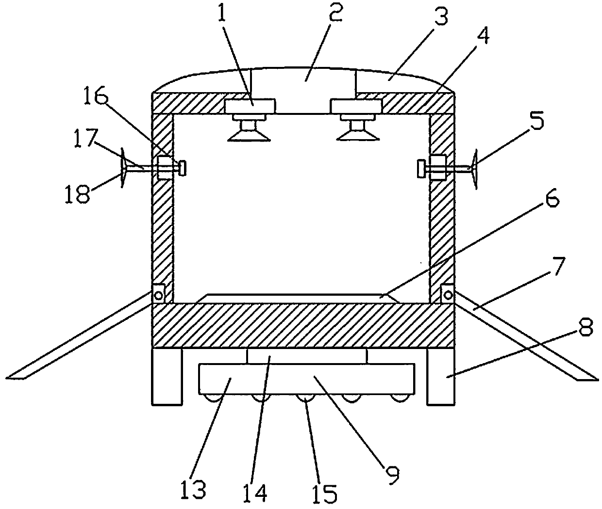
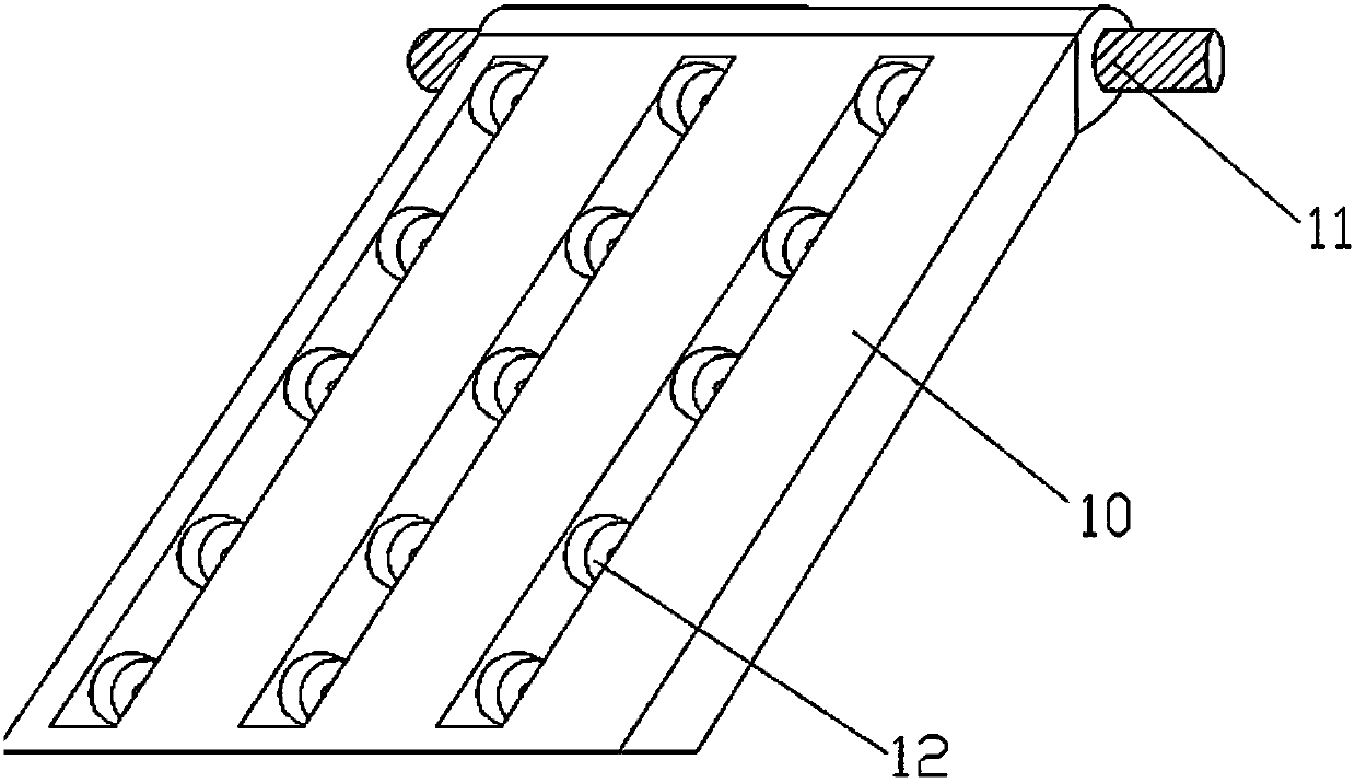
[0016] Figure 1-2 The specific embodiment of the present invention is shown: a machine base for electromechanical equipment, including an air injection device 1, a fan 2, a top cover 3, a machine base warehouse 4, a side wall ejector rod 5, an equipment mounting base 6, a warehouse door 7, and a machine base Warehouse pole 8 and lifting mobile device 9, top cover 3 is arranged on the top of machine base warehouse 4, blower fan 2 is arranged on the top of machine base warehouse 4, two air injection devices 1 are arranged on the top inside machine base warehouse 4, and the air injection device 1 is connected to the fan 2, the side wall ejector rod 5 is set on the side wall of the base compartment 4, the door 7 is set on the base compartment 4, the equipment mounting base 6 is set at the bottom of the base compartment 4, and the base compartment The pole 8 is arranged at the edge of the bottom of the base warehouse 4, and the lifting device 9 is arranged at the center of the bot...


PUM


Abstract

The invention discloses an electromechanical equipment mounting stand. The electromechanical equipment mounting stand comprises air spraying devices, a fan, a top cover, a stand bin, a side wall ejector rod, an equipment mounting base, a bin door, a stand bin support rod and a lifting moving device; the top cover is arranged at the top of the stand bin; the fan is arranged at the top of the standbin; two air spraying devices are arranged at the top end in the stand bin, and are connected with the fan; the side wall ejector rod is arranged on the side wall of the stand bin; the bin door is arranged on the stand bin; the equipment mounting base is arranged at the bottom end in the stand bin; the stand bin support rod is arranged on the bottom edge of the stand bin; and the lifting moving device is arranged in the bottom center of the stand bin. The electromechanical equipment mounting stand can achieve the functions of cooling and dedusting on electromechanical equipment through the fan, can stably fix the electromechanical equipment in the stand bin, can provide excellent mounting environment to the electromechanical equipment, and can realize easy movement of the electromechanicalequipment through the lifting moving device.

Description

technical field [0001] The invention relates to the field of electromechanical equipment, in particular to a machine base for installing electromechanical equipment. Background technique [0002] In order to ensure its bearing capacity, the installation base of electromechanical equipment generally has a relatively solid structure, and the movement of the base itself is relatively difficult. In addition, ordinary machine bases only have the function of installing electromechanical equipment and do not have other functions. [0003] For example, the patent CN201720010777.5 discloses an installation device for installing electromechanical equipment, including a hydraulic base, a base plate, a support column and a lifting column. The upper surface of the hydraulic base is provided with a lifting column, and the upper surface of the lifting column is provided with There is a bottom plate, the bottom plate is movably connected with the hydraulic base through the lifting column, a...

Claims


Application Information

Patent Timeline
IPC IPC(8): F16M11/04F16M11/26
Inventor 刘蓉恽清石晓华
Owner ZHENJIANG QILONG TECH CO LTD
Why Eureka
Try Eureka