Complicated narrow space deep foundation underground engineering combined inclination measuring method

A technology for underground engineering and deep foundations. It is applied in the direction of measuring inclination, measuring devices, surveying and navigation, etc. It can solve the problems of high cost of buried installation, errors, and delays in the construction period, and achieve convenient and economical construction, universal applicability, and simple calculation. Effect

Inactive Publication Date: 2018-01-19
HUNAN UNIV OF SCI & TECH
View PDF3 Cites 5 Cited by
  • Summary
  • Abstract
  • Description
  • Claims
  • Application Information

AI Technical Summary

Problems solved by technology

[0002] The construction site is complicated, and the ground space of the urban core area (viaduct) is narrow. The traditional one-stop deep foundation underground continuous pile (wall) steel cage skeleton is used for hoisting and lowering installation. There is no such a large space for hoisting and installation; After the concrete is cored to bury the inclinometer tube, the installation cost will be dozens of times higher, and the construction period will be seriously delayed, and the gaps around the re-buried inclinometer tube must be filled with fine sand, which has the problem of overall compactness. The actual deformation of the pit will be slightly affected by
Therefore, using conventional ideas for placement often makes the observation data discontinuous or distorted, wrong, or even unrealizable. Therefore, a deep foundation underground horizontal displacement monitoring and data processing method suitable for complex and narrow construction environments is needed.

Method used


Image

  • Complicated narrow space deep foundation underground engineering combined inclination measuring method
  • Complicated narrow space deep foundation underground engineering combined inclination measuring method
  • Complicated narrow space deep foundation underground engineering combined inclination measuring method

Examples


Embodiment Construction

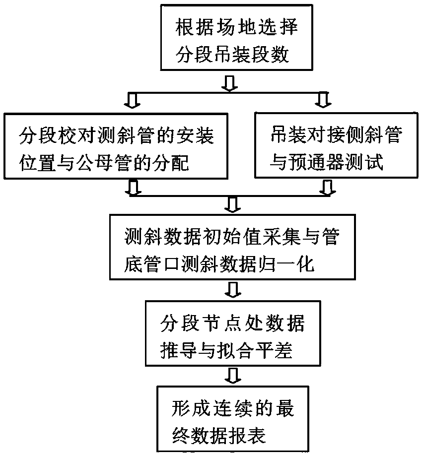
[0013] A combined inclinometer method for deep foundation underground engineering in complex and narrow spaces, comprising steps:

[0014] (1) Select the number of hoisting segments according to the site.

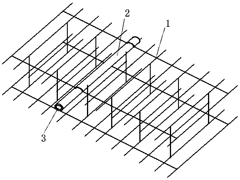
[0015] (2) Check the installation position of the inclinometer tube 2 and the distribution of male and female tubes in sections.

[0016] (3) Hoisting butt joint side inclined pipe 2 and pre-passer test.

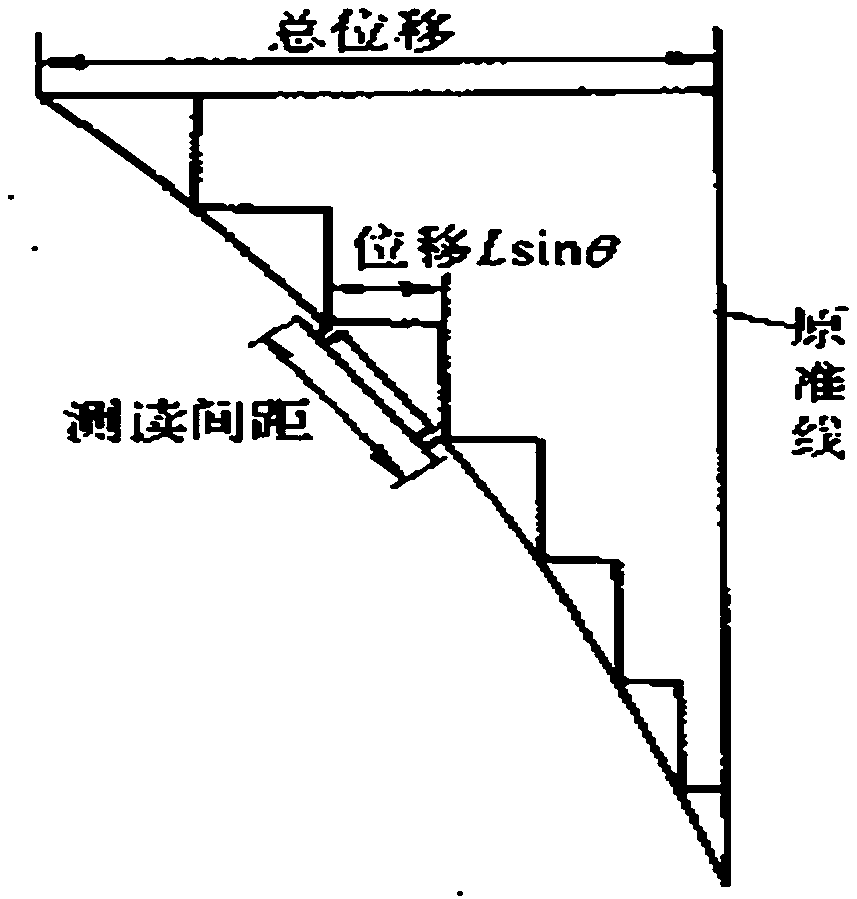
[0017] (4) Acquisition of the initial value of the inclinometer data and normalization of the inclinometer data at the pipe bottom and nozzle.

[0018] (5) Data derivation and fitting adjustment at segmented nodes.

[0019] (6) Form a continuous final data report.

[0020] The present invention lowers the reinforcement cage 1 of the retaining pile (wall) in sections, divides the entire inclinometer tube 2 into at least two sections and places them in the corresponding geometric positions of the reinforcement cage 1, and then rotates at the interface after the reinforce...


PUM


Abstract

The invention discloses a complicated narrow space deep foundation underground engineering combined inclination measuring method. A sectioned form is used for descending a fender post (wall) steel barcage; a whole inclination measuring pipe is divided into at least two sections to be respectively put in corresponding geometrical positions of the steel bar cage; after the steel bar cage is stablyput, the inclination measuring pipe is rotated in the connector position for butt joint; the two sections of inclination measuring pipes are respectively subjected to data collection and calculation;the lower section of inclination measuring pipe uses a bottom rock entering position as a calculation starting point; the upward sequential analogy is performed to the sectioning position; the upper section of the inclination measuring pipe uses a pipe opening as the calculation starting point; before the measurement in each time, a total station instrument is used for collecting the pipe openingposition change quantity; after the pipe opening position modification, the downward sequential analogy is performed to the sectioning position; then, the integral error compensation is fit to obtainthe final continuous inclination measuring data. The method provided by the invention has the advantages that the installation, the data collection, the operation and the calculation are simple; the precision is high; the construction is convenient and economic; the method is applicable to narrow-space complicated narrow construction sites incapable of realizing one-step hoisting; the general applicability is realized.

Description

technical field [0001] This patent relates to an improved combined inclinometer method for complex and narrow space deep foundation underground engineering. Background technique [0002] The construction site is complicated, and the ground space of the urban core area (viaduct) is narrow. The traditional one-stop deep foundation underground continuous pile (wall) steel cage skeleton is used for hoisting and lowering installation. There is no such a large space for hoisting and installation; After the concrete is cored to bury the inclinometer tube, the installation cost will be dozens of times higher, and the construction period will be seriously delayed, and the gaps around the re-buried inclinometer tube must be filled with fine sand, which has the problem of overall compactness. The actual deformation of the pit is slightly affected. Therefore, using conventional ideas for placement often results in discontinuous or distorted, erroneous, or even unrealizable observatio...

Claims


Application Information

Patent Timeline
Patent Type & Authority Applications(China)
IPC IPC(8): G01C9/00
Inventor 龙四春
Owner HUNAN UNIV OF SCI & TECH
Why Eureka
Try Eureka