Eureka AIR delivers breakthrough ideas for toughest innovation challenges, trusted by R&D personnel around the world.

Optical fiber adapter structure

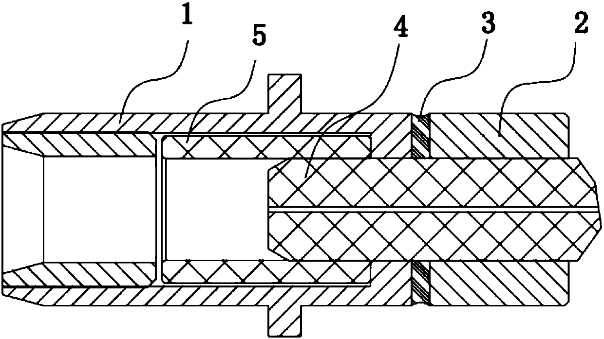
A fiber optic adapter and fiber optic ferrule technology, which is applied in the field of optical communication, can solve the problems of long length of fiber optic ferrule 4, insufficient electromagnetic shielding performance of the fiber optic adapter, and insufficient compact packaging of optical devices, so as to reduce electromagnetic wave leakage and ensure optical transmission. The effect of transmission

Active Publication Date: 2018-01-19
WUHAN TELECOMM DEVICES
View PDF5 Cites 6 Cited by
  • Summary
  • Abstract
  • Description
  • Claims
  • Application Information

AI Technical Summary

Problems solved by technology

[0008] The technical problem to be solved by the present invention is that the electromagnetic shielding performance of the existing optical fiber adapter is not good enough, and the length of the optical fiber pin 4 of the existing optical fiber adapter is relatively long, resulting in the technical problem that the packaging of the optical device is not compact enough

Method used


Image

  • Optical fiber adapter structure
  • Optical fiber adapter structure
  • Optical fiber adapter structure

Examples


Embodiment 1

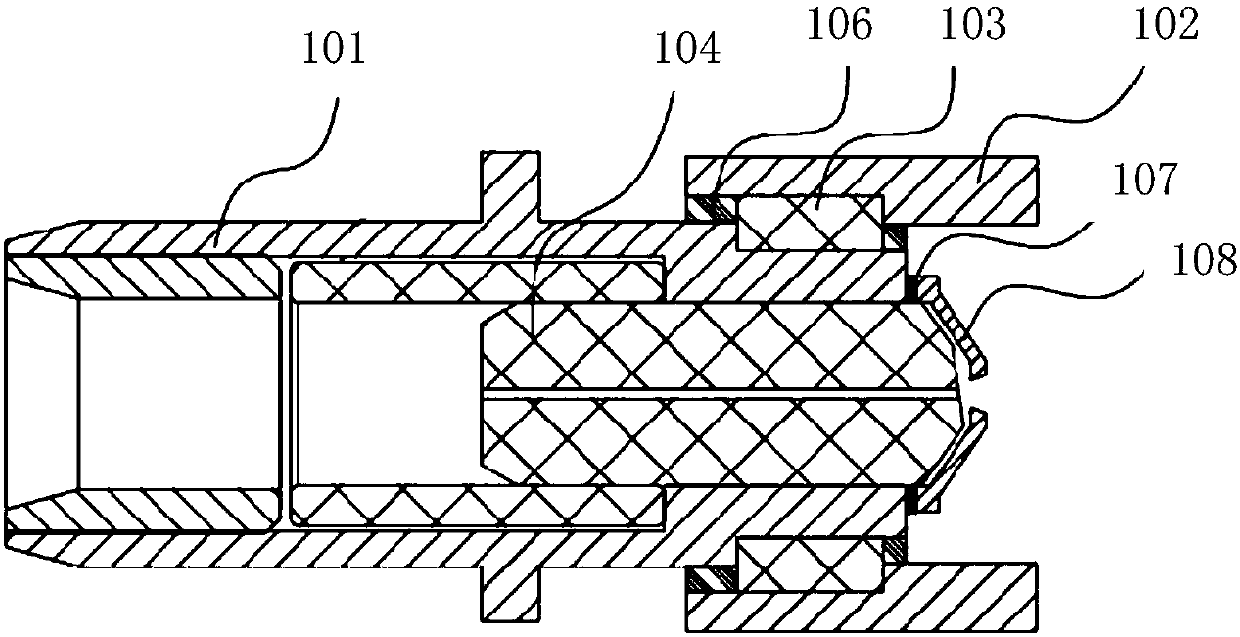
[0045] Embodiment 2 of the present invention provides an optical fiber adapter structure, such as figure 2 As shown, it includes a metal flange 101, a pipe body 102, an insulating ring 103, an optical fiber ferrule 104, and the structure also includes a shielding ring 108, specifically:

[0046] The optical fiber ferrule 104 is embedded in the metal flange 101, and the shielding ring 108 is fixed on the bottom of the metal flange 101 by conductive glue 107; wherein, the shielding ring 108 covers the ferrule 104 , and reserved a hole only for the laser signal to pass through;

[0047] The pipe body 102 is sleeved on the bottom of the metal flange 101 , and the insulation between the pipe body 102 and the metal flange 101 is realized by the insulating ring 103 .

[0048] The embodiment of the present invention provides an optical fiber adapter structure. The metal flange 101, the insulating ring 103 and the tube body 102 are radially assembled from the inside to the outside, w...

Embodiment 2

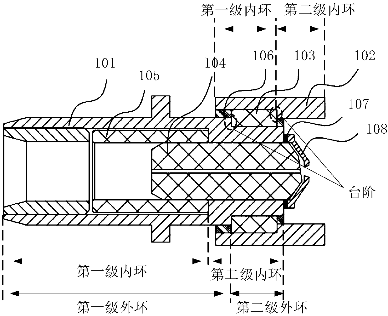
[0058] Embodiment 2 of the present invention provides an optical fiber adapter structure, such as image 3 As shown, it includes metal flange 101, pipe body 102, insulating ring 103, optical fiber ferrule 104 and sleeve 105, and the structure also includes insulating glue 106, conductive glue 107 and shielding ring 108, specifically:

[0059] The first-stage inner ring of the metal flange 101 is provided with the sleeve 105, and the second-stage inner ring is embedded with the pin 104, wherein the inner diameter of the second-stage inner ring is smaller than that of the first-stage inner ring , and the metal flange 101 is located on the outer wall of the second-level inner ring, and a second-level outer ring is provided, and the diameter length of the second-level outer ring is smaller than the first-level outer ring of the metal flange 101, and the The first-level outer ring is the outer wall of the main body of the metal flange 101; the metal flange 101 is located on the end...


PUM

PropertyMeasurementUnit
Apertureaaaaaaaaaa

Abstract

The invention relates to the technical field of optical communication, and provides an optical fiber adapter structure. The optical fiber adapter structure comprises a metal flange 101, a tube body 102, an insulating ring 103, an optical fiber inserting pin 104, and a shielding ring 108. The optical fiber inserting pin 104 is embedded into the metal flange 101. The shielding ring 108 is fixed at the bottom of the metal flange 101 through a conductive adhesive 107. The shielding ring 108 covers the end part of the inserting pin 104, and is provided with a reserved hole used for allowing only laser signals to pass through. The tube body 102 is connected with the bottom of the metal flange 101 in a sleeved mode. The insulation effect is achieved between the tube body 102 and the metal flange101 through the insulating ring 103. According to the invention, the shielding ring 108 made of conductive materials is adhered to the tail end of the metal flange 101 through the conductive adhesive107, and the complete electrical contact is maintained. The electromagnetic wave radiation between the interior of the optical device and the outside of the metal flange 101 is reduced.

Description

【Technical field】 [0001] The invention relates to the technical field of optical communication, in particular to an optical fiber adapter structure. 【Background technique】 [0002] Optical fiber communication systems are developing towards high speed and high port density. As one of the core components of optical fiber communication, optical devices are also facing these technical challenges. The more compact etc. [0003] At present, the frequency of signals processed by high-speed optical devices has reached 25 GHz, and the electromagnetic compatibility problems caused by high-frequency signals are very serious. In order to improve the influence of electromagnetic compatibility problems, optical fiber communication systems, high-speed optical modules, and optical devices usually use metal materials as housings, and at the same time minimize the gaps between housing components. Partially strengthen electromagnetic shielding and other means, and at the same time reduce the...

Claims


Application Information

Patent Timeline
IPC IPC(8): G02B6/38
CPCG02B6/3846G02B6/3825G02B6/3861
Inventor 陈序光胡强鹏张军陈志强朱虹梁坡
Owner WUHAN TELECOMM DEVICES
Why Eureka
Eureka Blog
Learn More