Detection method of electronic article surveillance equipment
An electronic detector and detection method technology, applied in the direction of electromagnetic radiation induction, etc., can solve the problems of different resonance frequencies, insignificant excitation effects, false alarms, etc., and achieve the effect of avoiding false alarms and avoiding the interference of external environmental electromagnetic signals
- Summary
- Abstract
- Description
- Claims
- Application Information
AI Technical Summary
Problems solved by technology
Method used
Image

Examples
Embodiment 1
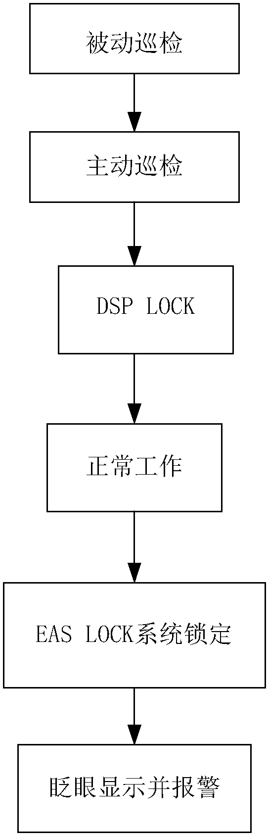
[0042] Such as Figure 1-2 Shown, the detection method of a kind of commercial electronic detector of the present invention comprises the steps:
[0043] Step A) Use the device receiving unit to obtain external electromagnetic environment information, and analyze the external electromagnetic environment information to obtain a phase point where the interference environment is clean, and the phase point at this time is used as the working point A; the phase point is the phase point of the AC signal of the power supply.
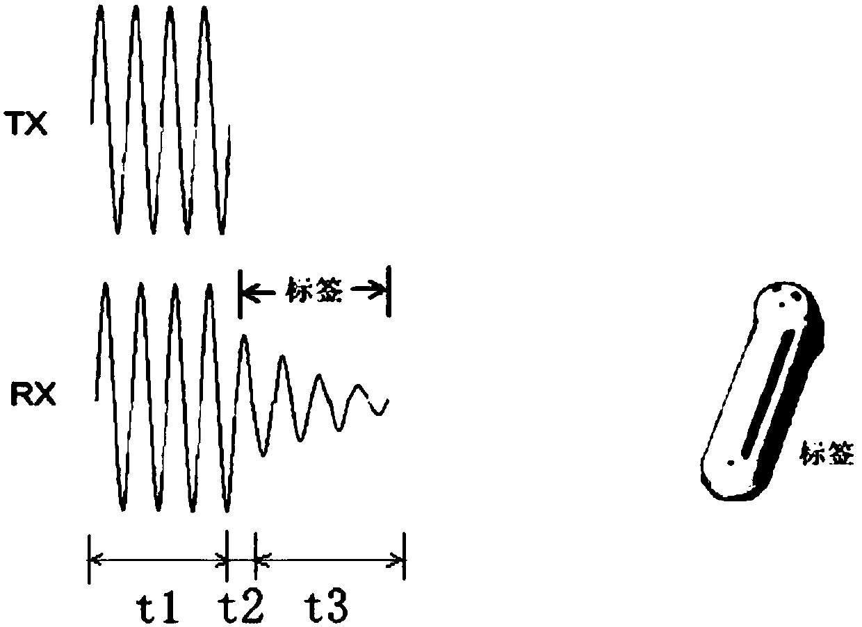
[0044] Step B) Use DSP LOCK digital signal processing technology to lock the one or more working points A, when locking the above working point A for normal operation, the device transmitting unit works in the t1 period in front of the above working point A, so that the receiving unit is just at Working point A, that is, period t3;
[0045] Step C) Normal work: Under the condition of locking the working point, the transmitting unit of the device works, and tra...
Embodiment 2
[0051] The present embodiment is preferably as follows on the basis of embodiment 1: the concrete process of step A) is:
[0052] Passive inspection: The receiving unit of the equipment is started, and the surrounding environment is electromagnetically scanned by a static scanning method, and multiple electromagnetic wave signals are obtained. In multiple cycles, the one with the least interference is found from all the phase points formed by multiple electromagnetic wave signals Or multiple phase corresponding points, as the working point A. Multiple cycles refer to multiple consecutive cycles in the AC signal of the power supply. For the method of finding the working point A, take the time range of 50Hz and 40ms as an example to illustrate. One cycle time of 50Hz is 20ms, and 40ms is 2 cycle, the working point A in this scheme is the phase corresponding to the same time point in every two cycles, which is the low point of interference compared with other phases in this cycle...
Embodiment 3
[0054] The present embodiment is preferably as follows on the basis of the foregoing embodiments: the concrete process of step A) is:
[0055] Passive inspection: The receiving unit of the equipment is started, and the surrounding environment is electromagnetically scanned by a static scanning method, and multiple electromagnetic wave signals are obtained. In multiple cycles, the one with the least interference is found from all the phase points formed by multiple electromagnetic wave signals Or multiple phase corresponding points, all as working point B;
[0056] After the passive inspection is completed, the active inspection is also included: in front of the working point B, the equipment transmitting unit is started to transmit the main frequency which is the same as the frequency of the commodity electronic tag, and the equipment receiving unit receives the reflected signals of the main frequency corresponding to all the working points, Analyze the amplitude of the main f...
PUM
 Abstract
Description
Claims
Application Information
 - R&D
- Intellectual Property
- Life Sciences
- Materials
- Tech Scout
- Unparalleled Data Quality
- Higher Quality Content
- 60% Fewer Hallucinations
Browse by: Latest US Patents, China's latest patents, Technical Efficacy Thesaurus, Application Domain, Technology Topic, Popular Technical Reports.
© 2025 PatSnap. All rights reserved.Legal|Privacy policy|Modern Slavery Act Transparency Statement|Sitemap|About US| Contact US: help@patsnap.com